Display device

a technology of a display device and a display screen, which is applied in the direction of identification means, television systems, instruments, etc., can solve the problems of driving restrictions and unable to watch images during the travel of the vehicl

Inactive Publication Date: 2005-10-11
ALPINE ELECTRONICS INC
View PDF13 Cites 43 Cited by
  • Summary
  • Abstract
  • Description
  • Claims
  • Application Information

AI Technical Summary

Benefits of technology

[0009]To overcome the foregoing problems, the present invention provides a display device including a display section, and a viewing angle control shutter for switching between a first state in which an image displayed in a display range of at least one part of the display section is visible from both of a first direction and a second direction, and a second state in which the image is visible from only one of the first direction and the second direction.
[0010]In another embodiment, the present invention provides a display device that is mounted on the vehicle, including a display section, a viewing angle control shutter for switching between a first state in which an image displayed in a display range of at least one part of the display section is visible from both of a first direction and a second direction, and a second state in which the image is visible from only one of the first direction and the second direction, a video signal switching and synthesizing section for switching between or synthesizing a plurality of video signals to transmit the switched or synthesized video signal to the display section, and for supplying a control signal responsive to the video signal transmitted to the display section. A shutter dri

Problems solved by technology

However, for safety reasons, a driver is prohibited from watching the images of a movie, a TV and the like while the vehicle is traveling.
Therefore, although a passenger

Method used


Image

  • Display device
  • Display device
  • Display device

Examples


first embodiment

(First Embodiment)

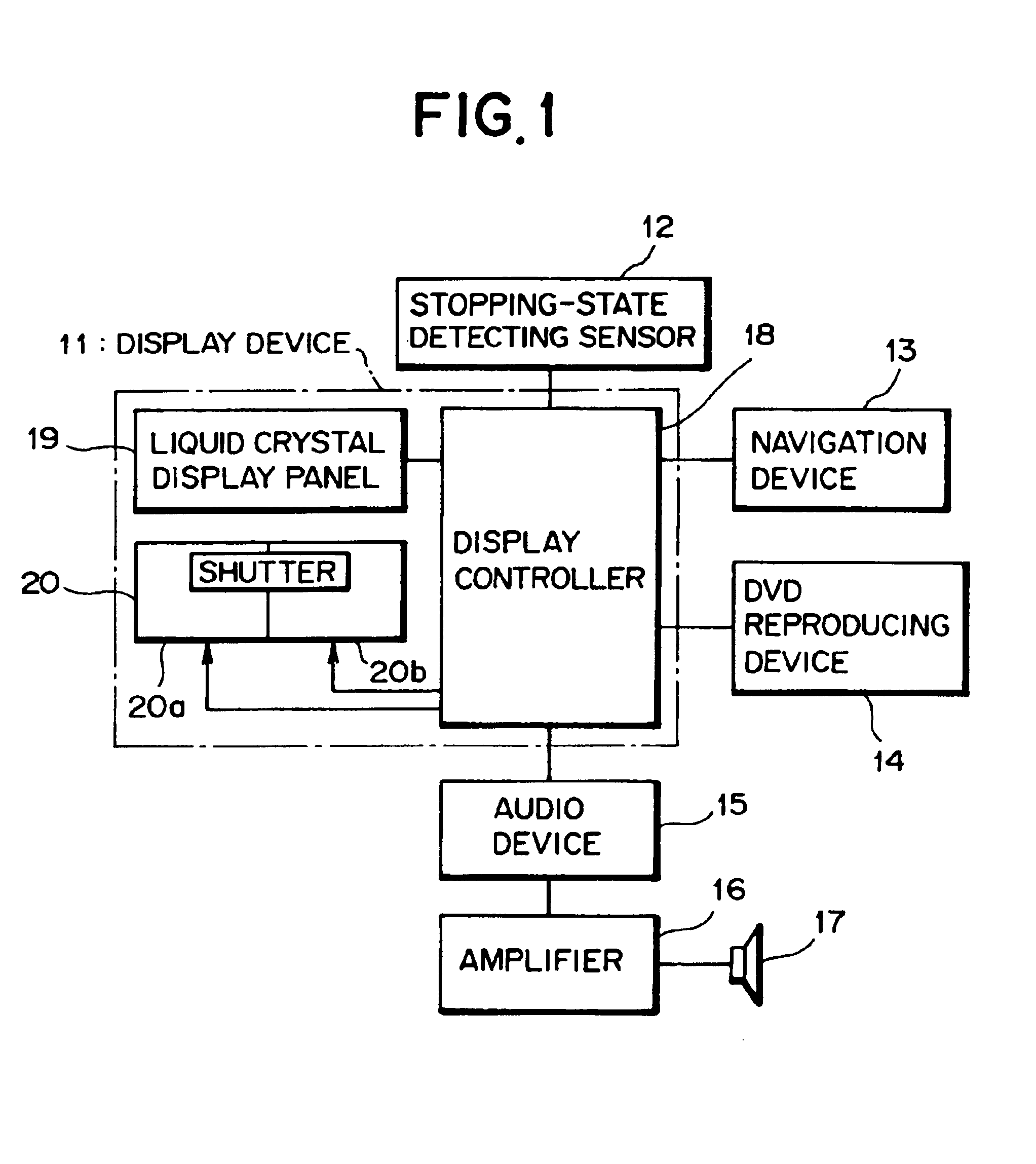
[0025]FIG. 1 is a block diagram showing the configuration of an audiovisual (AV) and vehicle navigation system using a display device of a first preferred embodiment in accordance with the present invention.

[0026]Referring now to FIG. 1, the AV and vehicle navigation system includes a display device 11, a stopping-state detecting sensor 12, a navigation device 13, a DVD reproducing device 14, an audio device 15, an amplifier 16, and a speaker 17. The display device 11 may be connected to other video devices such as a TV tuner and the like. However, to simplify the following explanation of the system, in this embodiment the display device 11 is connected only to the navigation device 13 and the DVD reproducing device 14, each of which is provided as a video device.

[0027]The stopping-state detecting sensor 12 is a sensor that detects whether or not the vehicle is in a stopping state. As examples, such a stopping-state detecting sensor 12 can be a speed sensor for det...

second embodiment

(Second Embodiment)

[0047]FIG. 8 is a block diagram showing the configuration of an AV and vehicle navigation system using a display device of a second preferred embodiment in accordance with the present invention; FIG. 9 is a schematic view showing the construction of the viewing angle control shutter of the second preferred embodiment; and FIG. 10 is a block diagram showing the configuration of a display controller of the second preferred embodiment. Note that in FIG. 8 and FIG. 10 the same components as those shown in FIG. 1 and FIG. 3 are given the same reference characters, respectively, and are not explained in detail hereunder.

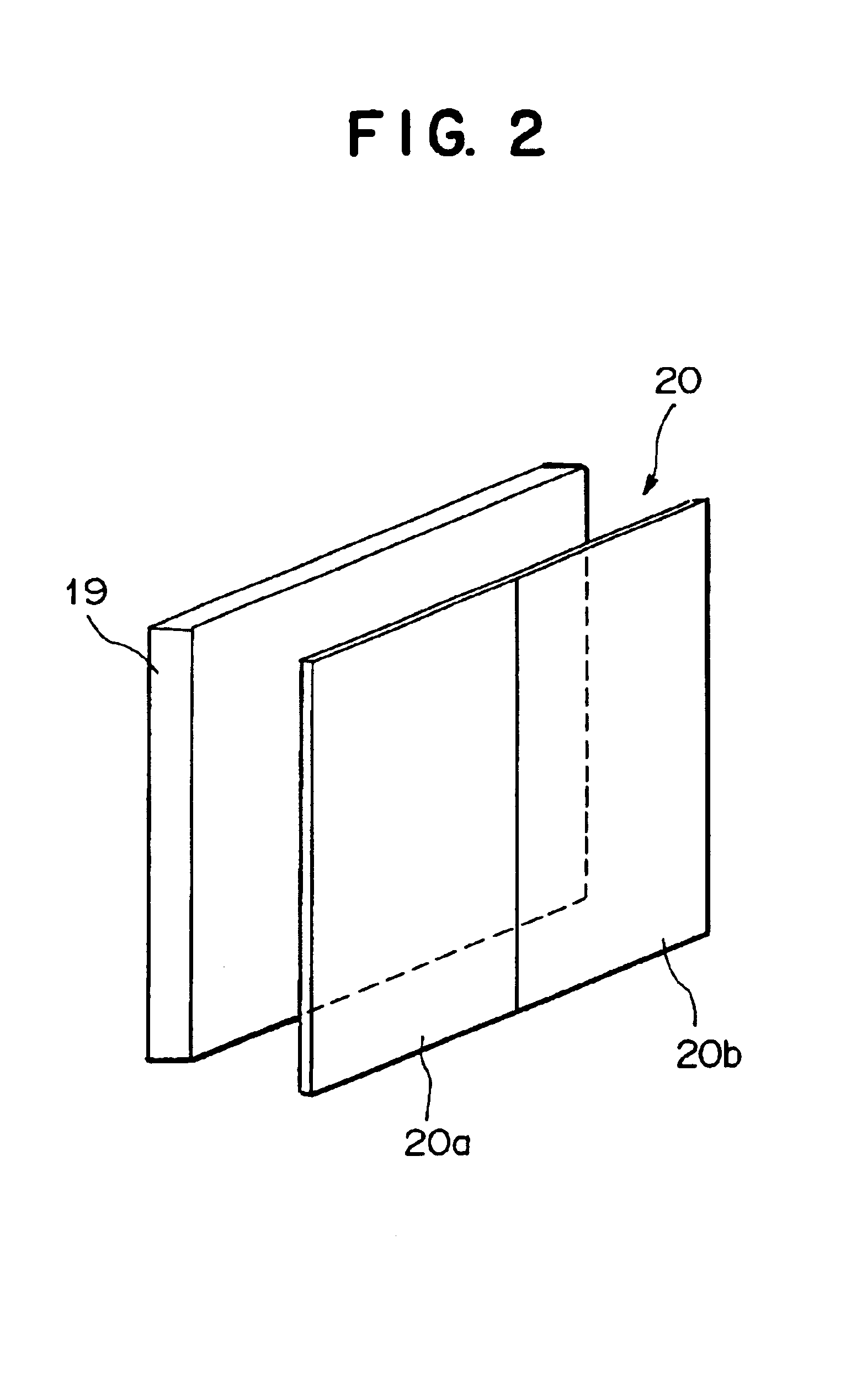
[0048]First, referring now to FIG. 9, a viewing angle control shutter 42 will be explained. The viewing angle control shutter 42 is disposed on the display screen of the liquid crystal display panel 19, and has a plurality of shutter cells corresponding to the respective pixels of the liquid crystal display panel 19. These shutter cells can tilt the liqu...

third embodiment

(Third Embodiment)

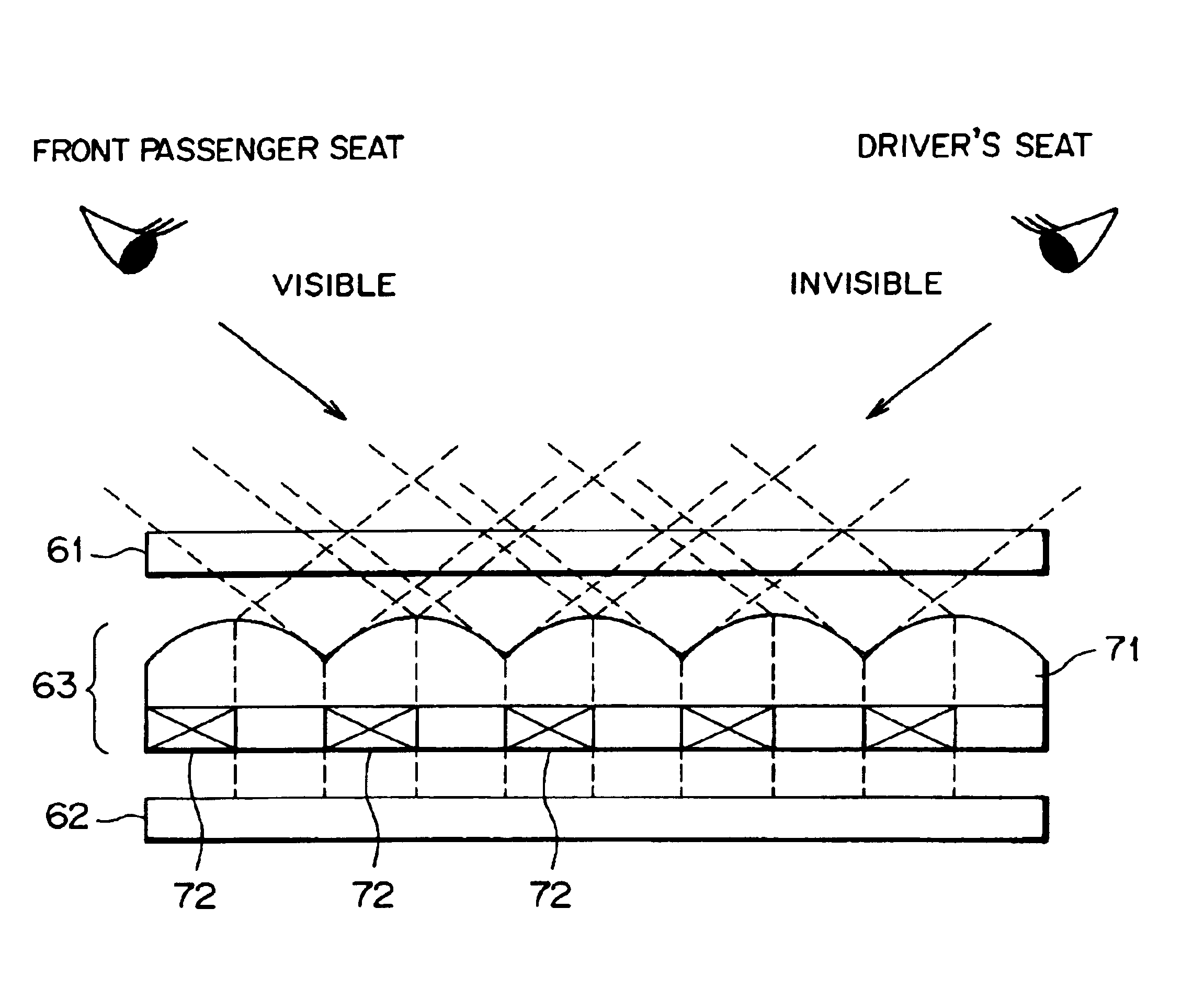
[0053]FIG. 12 is a schematic diagram showing the construction of a display device of a third preferred embodiment in accordance with the present invention. It should be, however, noted that the same display controller as that explained in the first embodiment or the second embodiment can be used in the third embodiment, thus omitting the explanation of the display controller.

[0054]In this embodiment, there is provided a viewing angle control shutter 63 between a liquid crystal display panel 61 and a backlight 62. The viewing angle control shutter 63 includes a plurality of cylindrical lenses 71 that are arranged side by side, and a plurality of shutter cells 72. In the case where the shutter cells 72 are in the off state, light emitted from the backlight 62 is divided into a light beam traveling toward the driver's seat and a light beam traveling toward the front passenger seat by the cylindrical lenses 71. These light beams pass through the liquid crystal display ...


PUM


Abstract

A display device is provided for making images of a movie, a TV or the like invisible to a driver while the vehicle is traveling, but at the same time visible to a passenger riding in a front passenger seat. A viewing angle control shutter 20 using a liquid crystal is disposed facing a front surface of a liquid crystal display panel 19. When the vehicle is in a stopping state, the viewing angle control shutter 20 is set to off, thereby making the image that is displayed on the display panel 19 visible from the driver's seat side and the front passenger seat side. While the vehicle is traveling, the viewing angle control shutter 20 is driven such that the driver can watch an image produced by the navigation device 13, but cannot watch an image reproduced by a DVD reproduction device 14.

Description

BACKGROUND OF THE INVENTION[0001]1. Field of the Invention[0002]The present invention relates to a display device capable of switching between a state in which an image is visible from one direction and a state in which the image is invisible from the one direction, while maintaining a state in which the image is visible from another specific direction. More particularly, the present invention relates to a display device suitable for a vehicle-mounted display device connected to a video signal output device (hereunder, referred to as “video device”) such as a navigation device or a DVD reproducing device.[0003]2. Description of the Related Art[0004]Vehicles are equipped with not only audio devices such as a radio and a CD player, but also video devices such as a navigation device, a television (TV) tuner, and a DVD reproducing device. Accordingly, the vehicles are also provided with display devices for displaying the images, such as a liquid crystal display panel and the like.[0005]...

Claims


Application Information

Patent Timeline
IPC IPC(8): B60K35/00H04N7/00G02F1/133G02F1/13G01C21/00B60R11/02G01C21/36G08G1/0969G09F9/00G09G5/00H04N5/72
CPCB60K35/00G02F1/1323G09G3/003H04N7/002B60K2350/901B60K2350/903G02F1/1347B60K2370/736B60K2370/739
Inventor OGINO, TAKAYUKI
Owner ALPINE ELECTRONICS INC
Why Eureka
Try Eureka