Backlight module for homogenizing the temperature of a flat panel display device

Inactive Publication Date: 2005-10-11
AU OPTRONICS CORP
View PDF19 Cites 29 Cited by
  • Summary
  • Abstract
  • Description
  • Claims
  • Application Information

AI Technical Summary

Benefits of technology

[0007]The object of the present invention is to provide a backlight module to improve the temperature distributio

Problems solved by technology

However, the heat produced from the light sources or backlight modules results in another problem for the display quality of the flat panel display devices.
However, this kind of arrangement often causes deterioration of the display quality of flat display panel devices since the distribution of the temperature on the lightguide or the reflector

Method used


Image

  • Backlight module for homogenizing the temperature of a flat panel display device
  • Backlight module for homogenizing the temperature of a flat panel display device

Examples


Embodiment Construction

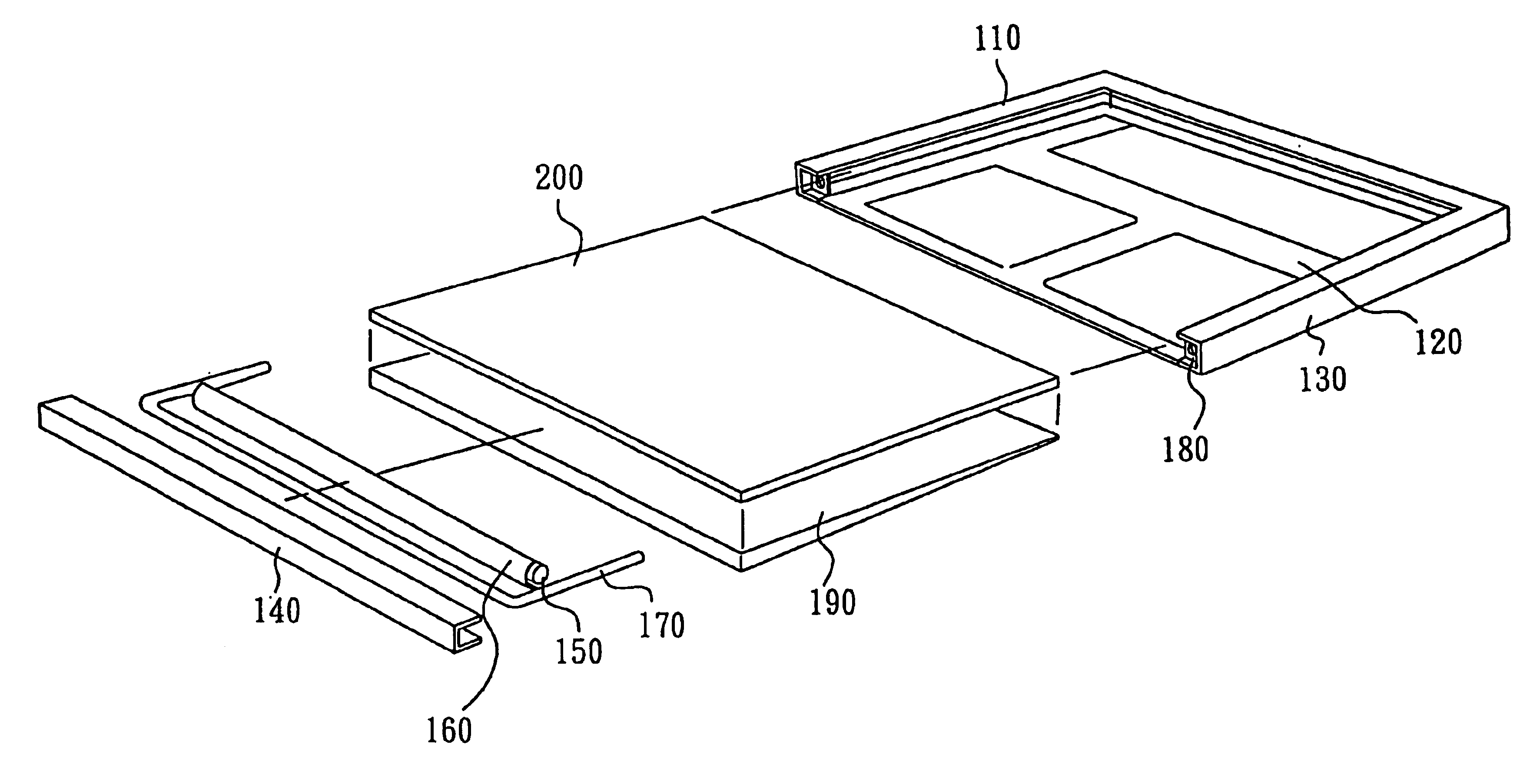
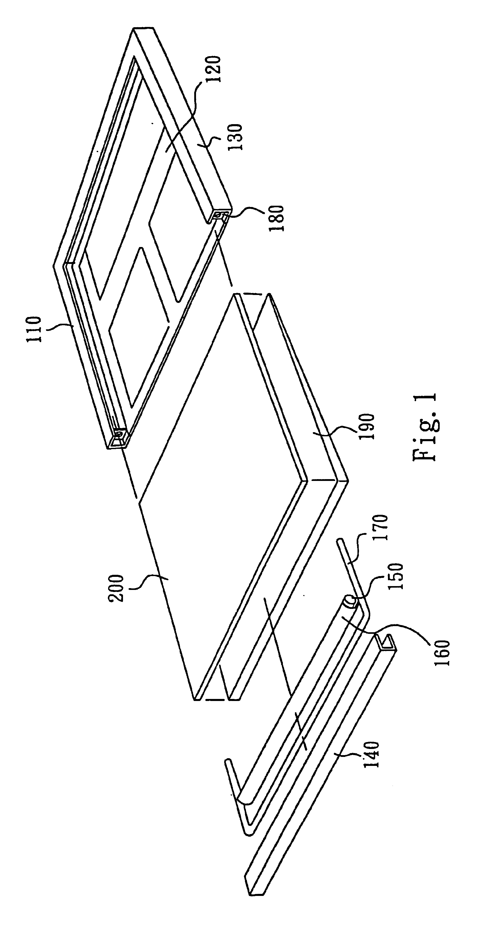
[0015]The heat pipe of flat panel display device of the present invention can be any conventional heat pipe. The heat pipe is a closed pipe with capillaries. Inside the heat pipe, there is filled with some recycled fluid (e.g. water) having low thermal resistance. The fluid (e.g. water) is evaporated as the heat is absorbed at the hot part of the heat pipe. The evaporated fluid (e.g. water) diffuses out to the cool part of the heat pipe. In most cases, the evaporated fluid (e.g. water) is condensed to fluid at the cool part of the heat pipe. The cooled fluid flows back to the hot part through the assistance of capillaries. Through the cycle of the fluid inside the heat pipe, heat can be carried out and the distribution of the temperature can be homogenized. The heat pipe sometimes is called micro heat pipe or micropipe. The length of the heat pipe of flat panel display device of the present invention is not limited. Preferably, the length of the heat pipe of flat panel display devic...


PUM


Abstract

A flat panel display or a backlight module for homogenizing temperature distribution. The backlight module utilizes a heat pipe to carry out the heat from the light source quickly and homogenizes the distribution of temperature of the light source.

Description

BACKGROUND OF THE INVENTION[0001]1. Field of the Invention[0002]The present invention relates to a flat panel display device or a backlight module and, more particularly, to a flat panel display device or a backlight module by using a heat pipe to homogenize the temperature of the flat panel display device.[0003]2. Description of Related Art[0004]Flat panel display devices are popular in recent years. Many flat panel display devices (e.g. liquid crystal display devices) are mounted with light sources (e.g. CCFLs or LEDs) or backlight modules for providing light for displaying images in dark environments. However, the heat produced from the light sources or backlight modules results in another problem for the display quality of the flat panel display devices.[0005]In most cases, a backlight module for a flat panel display device includes a reflector, a light source and a lightguide. The light source (e.g. a CCFL (cold cathode fluorescent lamp)) often locates in the cavity of the refl...

Claims


Application Information

Patent Timeline
IPC IPC(8): G02F1/1335G02F1/133G02F1/13G02F1/13357G09F9/00
CPCG02F1/133382G02F1/133615G02F1/133385
Inventor LIU, CHEN-HUACHANG, JUI-CHUANLEE, KUO-CHUNGSUN, KAI-YU
Owner AU OPTRONICS CORP
Why Eureka
Try Eureka