Tool for shaping and/or partially press hardening a workpiece and method for shaping and/or partially press hardening a workpiece

Active Publication Date: 2017-11-09
THYSSENKRUPP STEEL EURO AG +1
View PDF7 Cites 1 Cited by
  • Summary
  • Abstract
  • Description
  • Claims
  • Application Information

AI Technical Summary

Benefits of technology

The invention is a tool used for shaping and heat treatment of workpieces. The tool has a heat conducting system with a heat source, which is either inside or outside the tool. The heat source is surrounded by a thermal oil or melt, which ensures even heat distribution and uniform warming of the surface of the workpiece. The heat source can be easily positioned more flexibly, and the tool can be used in "tailored tempering" to provide different heat distribution in different tool segments. The heat source can be disposed within the heat conducting system without the need for a direct connection, making maintenance works easier. The heated surface of the tool enters into contact with the workpiece during shaping, and the heat source can be released from the tool without great effort. The heat conducting system can have a main channel or multiple supply channels with heat sources arranged at regular distances apart. The tool can also have a base plate with a heat source arranged on it, and the heat sources can be easily removed from the tool without great effort.

Problems solved by technology

Moreover, it is often, for design reasons, not possible to arrange the heating cartridge such that a desired heat output arrives at a specific place.
Since the heating cartridges, however, are inserted with fit into the tool, the high temperatures often give rise to integrally bonded connections between the heating cartridge and the tool, whereby a release of the heating cartridge from the tool is made more difficult.

Method used


Image

  • Tool for shaping and/or partially press hardening a workpiece and method for shaping and/or partially press hardening a workpiece
  • Tool for shaping and/or partially press hardening a workpiece and method for shaping and/or partially press hardening a workpiece

Examples


Embodiment Construction

[0014]In the various FIGURES, same parts are always provided with the same reference symbols and are therefore generally also named or mentioned only once in each case.

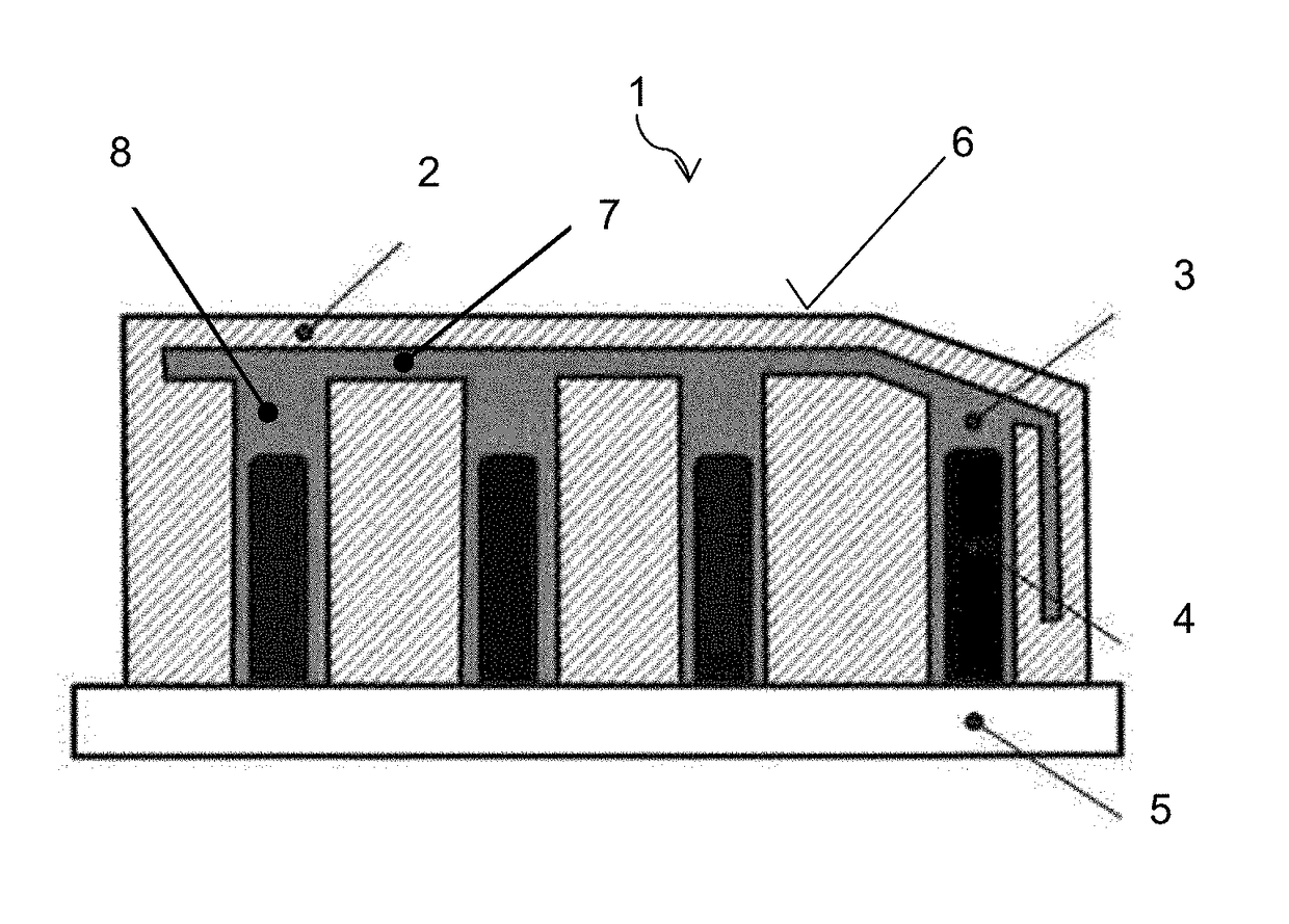
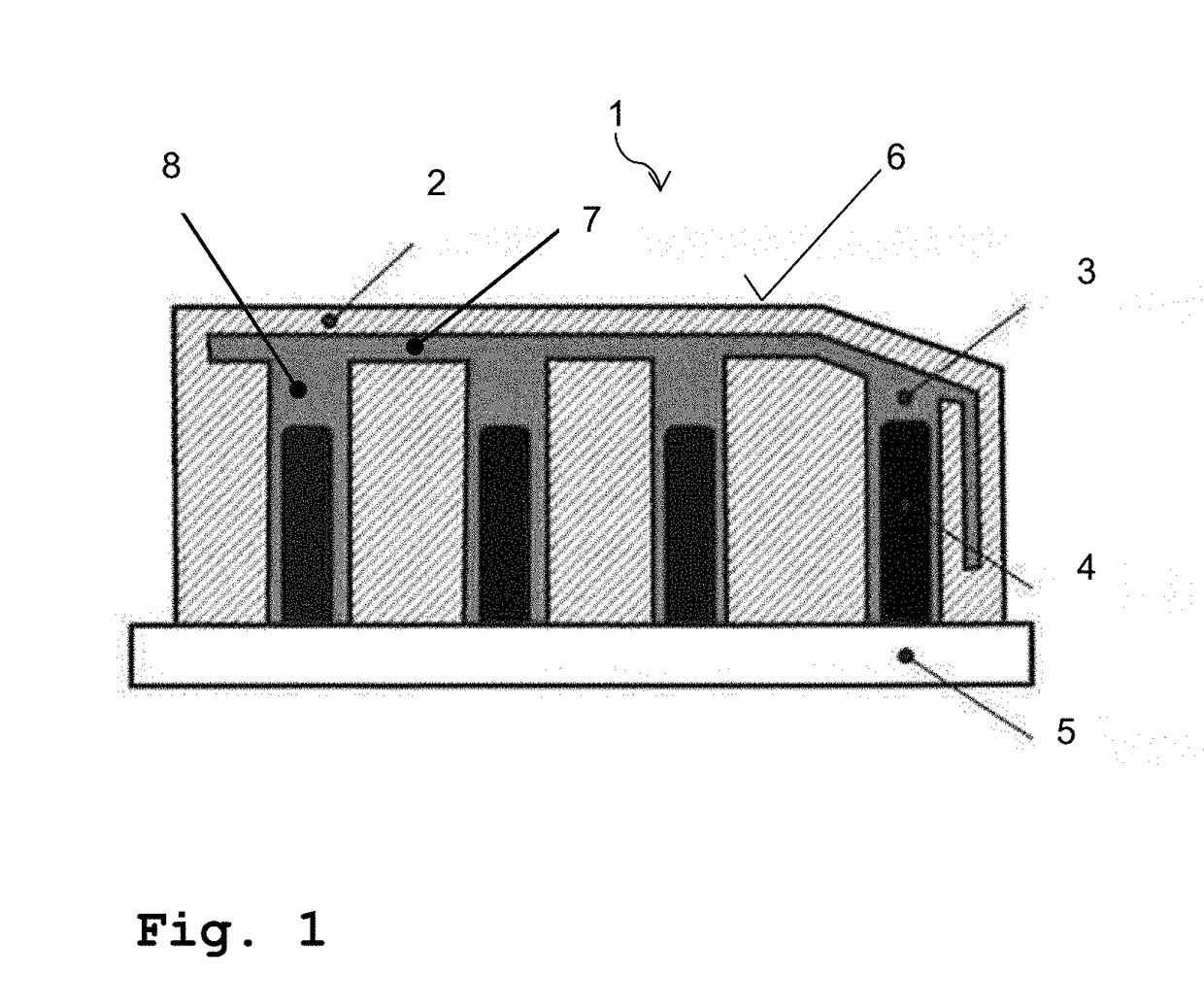
[0015]In FIG. 1, a tool 1 according to an exemplary embodiment of the present invention is represented. It is here preferably provided that this is constituted by a tool 1 for shaping, in particular hot shaping and / or partial press hardening. For instance, with the tool 1, workpieces (not represented here) made of a manganese-boron steel or of a composite, in particular TriBond, are shaped. For this the tool 1 comprises a main body 2, on the workpiece-facing side of which can be found a surface 6, which enters into contact with the workpiece in the course of the shaping. It is here further provided that this surface 6 of the tool 1 has an operating temperature of more than 400° C., in particular an operating temperature between 500° C. and 550° C., when the workpiece is deformed or shaped by the tool 1. In addition, i...


PUM

PropertyMeasurementUnit
Electrical conductoraaaaaaaaaa
Heataaaaaaaaaa
Thermal propertiesaaaaaaaaaa

Abstract

A tool may be used to shape and / or partially press harden a workpiece. In some examples, the tool may comprise a main body having a surface, as well as a heat conducting system containing a thermal medium. The heat conducting system is integrated in the tool in such a way that, for the heating of the surface, a heat radiating from a heat source is conducted by means of the heat conducting system to the surface of the main body. Further, the heat conducting system may comprise a thermal oil or a melt as the thermal medium. The surface of the main body may be configured to face the workpiece during the shaping or partial press hardening of the workpiece.

Description

PRIOR ART[0001]The present invention relates to a tool for shaping and / or partially press hardening a workpiece and to a method for shaping and / or partially press hardening a workpiece.[0002]In the hot shaping or press hardening of manganese-boron steels and possible composites, such as, for example, TriBond®, tempered tools are used to locally reduce the cooling rate. As a result of the reduced cooling rate, an improved ductility is locally established on the thus treated workpiece. Locally, tool surface temperatures of more than 400° C., preferably between 500° C. and 550° C., are sought. Also light metals, such as aluminum and magnesium, for instance, are shaped in tempered tools at temperatures of more than 150° C. As a rule, electrically operated heating cartridges, which directly deliver their thermal energy into the tool steel, are used for the local tempering of the tools. Consequently, high temperature differences of more than 200° C., can be generated along the surface whi...

Claims


Application Information

Patent Timeline
IPC IPC(8): B21D22/02C21D1/673B21D37/16
CPCB21D22/022C21D1/673B21D37/16C21D1/06B21D22/06B21D22/208B21D35/001
Inventor SIKORA, SASCHAGRAFF, STEPHANEBANIK, JANKO
Owner THYSSENKRUPP STEEL EURO AG
Why Eureka
Try Eureka