Aerodynamic trip to improve acoustic transmission loss and reduce noise level for gas turbine engine

Inactive Publication Date: 2007-05-03
PRATT & WHITNEY CANADA CORP
View PDF1 Cites 7 Cited by
  • Summary
  • Abstract
  • Description
  • Claims
  • Application Information

AI Technical Summary

Benefits of technology

[0009] The principle behind the invention is the decoupling of compressor pressure fluctuations and combustor low frequency noise signals by tripping the hot gas flow from the combustor by means of a relatively small volume of cross flow air. Incoming cross flow of air creates a step change in the direction of flow. As a consequence the promotion of regional turbulence by the cross flow of air enhances mixing thereby improving the overall temperature distribution at the turbine stage as well as decoupling between the attenuation and the pressure fluctuation within the compressor and the attenuation and pressure fluctuations in the combustor.

Problems solved by technology

This has not been found to be the case but rather the combustor itself is a source of far field low frequency noise.
Noise reduction techniques are of course well known however to date there appears to be no recognition that pressure fluctuations at the compressor exit are coupled with low frequency noise from the combustor.

Method used


Image

  • Aerodynamic trip to improve acoustic transmission loss and reduce noise level for gas turbine engine
  • Aerodynamic trip to improve acoustic transmission loss and reduce noise level for gas turbine engine
  • Aerodynamic trip to improve acoustic transmission loss and reduce noise level for gas turbine engine

Examples


Embodiment Construction

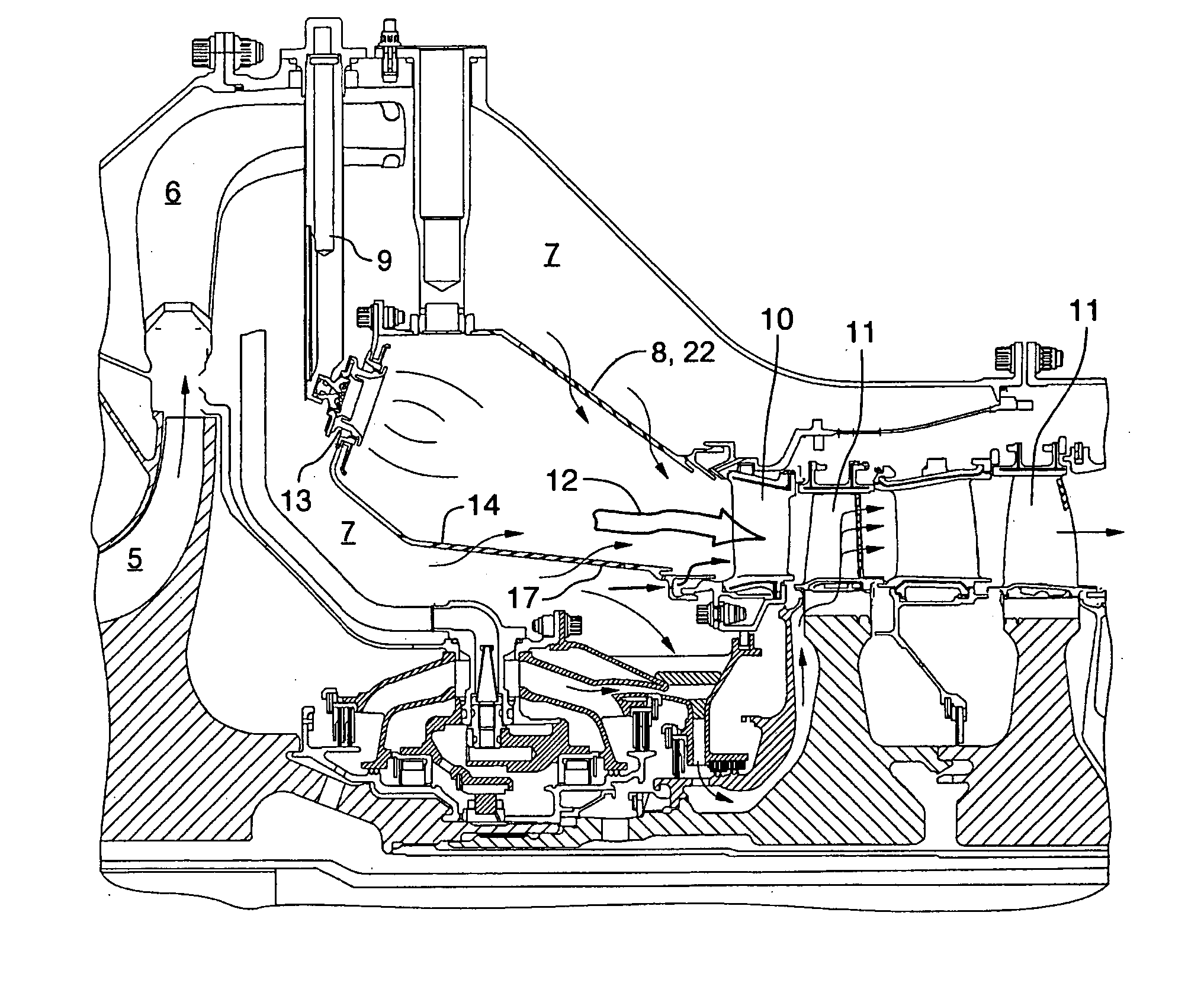
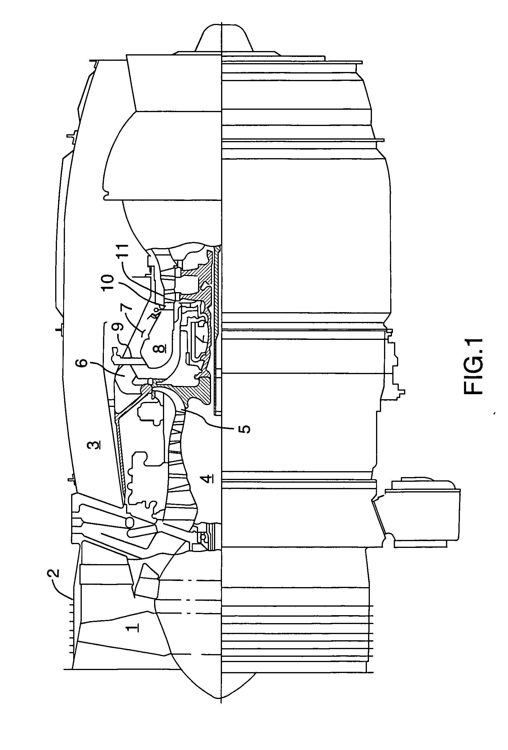
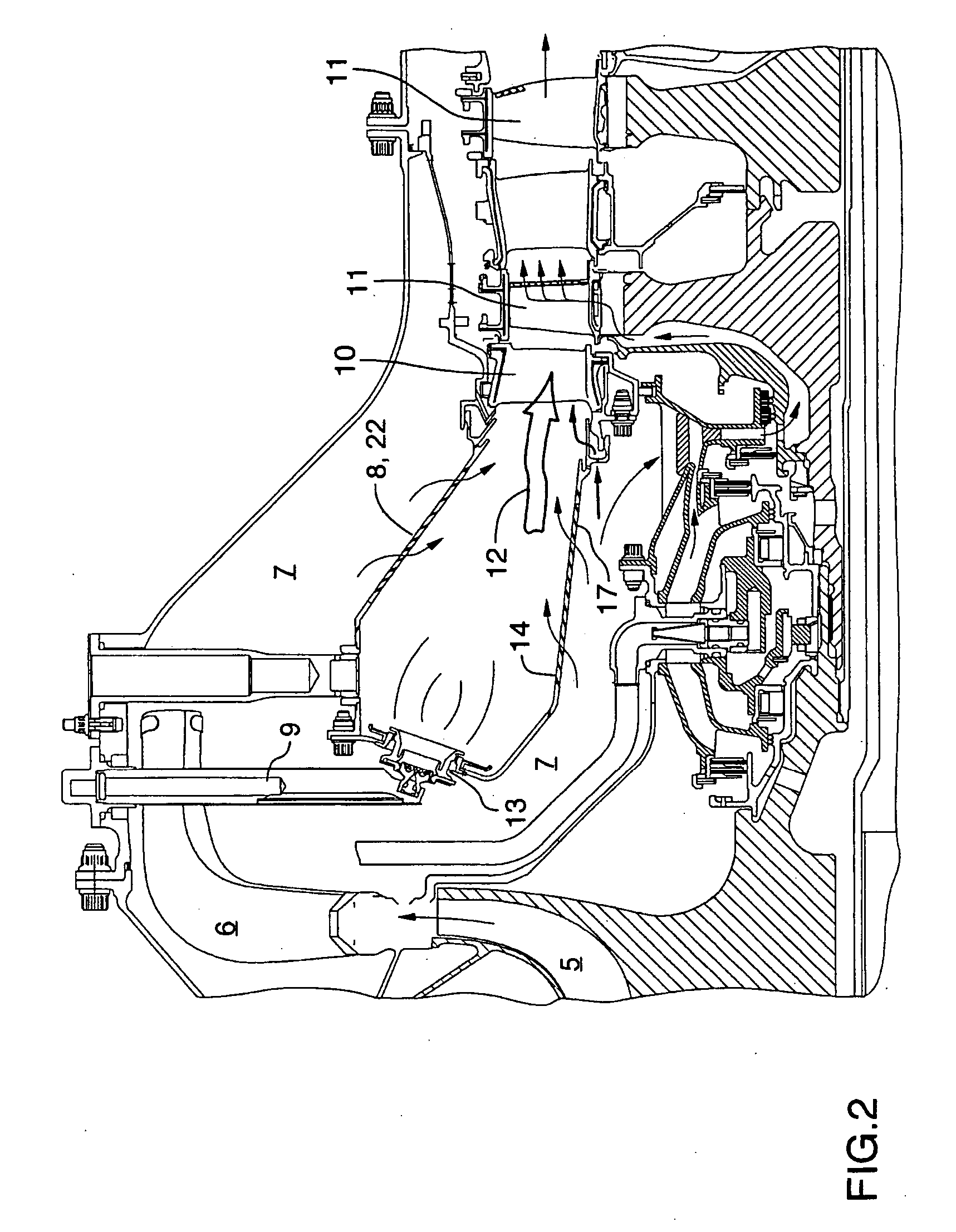
[0020]FIG. 1 shows an axial cross-section through a turbo fan gas turbine engine. It will be understood however that the invention is applicable to any type of engine with a combustor and turbine section such as for example turbo shaft, turbo prop, or auxiliary power units. Air intake into the engine passes over fan blades 1 surrounded by a fan case 2. The air is split into an outer annular flow which passes through the bypass duct 3 and an inner flow which passes through the low-pressure axial compressor 4 and high-pressure centrifugal compressor 5. Compressed air exits the compressor through diffuser 6 and is contained within a plenum 7 that surrounds the combustor 8. Fuel is supplied through the combustor 8 through fuel tubes 9 which is mixed with air from the plenum 7 as it sprays through nozzles into the combustor as a fuel air mixture that is ignited. At portion of the compressed air within the plenum 7 is admitted into the combustor 8 through orifices in the side walls to cre...


PUM


Abstract

A method and device for decoupling combustor attenuation and pressure fluctuation from turbine attenuation and pressure fluctuation in a gas turbine engine. The engine has: a compressor; a combustor; and a turbine, that generate a flow of hot gas from the combustor to the turbine. An aerodynamic trip is disposed in at least one of; a combustor wall; and an inner shroud of the nozzle guide vane ring, and is adapted to emit jets of compressed air from cross flow ports into the flow of hot gas from the combustor. The air jets from the cross flow ports increase turbulence and equalize temperature distribution in addition to decoupling the attenuation and pressure fluctuations between the combustor and the turbine.

Description

TECHNICAL FIELD [0001] The invention relates to a method and device for decoupling combustor attenuation and pressure fluctuation from turbine attenuation and pressure fluctuation in a gas turbine engine. BACKGROUND OF THE ART [0002] Gas turbine engines are required to perform at low emission levels and low noise levels during full power operation. Ideally any modifications made to a combustor to achieve lower emission levels or lower noise levels do not involve any compromise in durability or reliability. [0003] At the compressor exit, testing indicates that pressure fluctuations include a mix of broadband low frequency signals and high frequency signals that are not solely attributable to acoustic causes. Attenuation of a broadband low and high frequency signals occurs in the combustion chamber and signals are dissipated in the turbine stage. At all engine speeds tone free low frequency signal are generated by the combustor. Pure acoustic propagation would show that combustor freq...

Claims


Application Information

Patent Timeline
IPC IPC(8): F02C7/24F01D9/02
CPCF01D9/023
Inventor ALKABIE, HISHAM
Owner PRATT & WHITNEY CANADA CORP
Why Eureka
Try Eureka