
Enhanced Electrical Contact to Microbes in Microbial Fuel Cells

Active Publication Date: 2008-10-23
UNIV OF FLORIDA RES FOUNDATION INC
View PDF2 Cites 16 Cited by
  • Summary
  • Abstract
  • Description
  • Claims
  • Application Information

AI Technical Summary

Benefits of technology

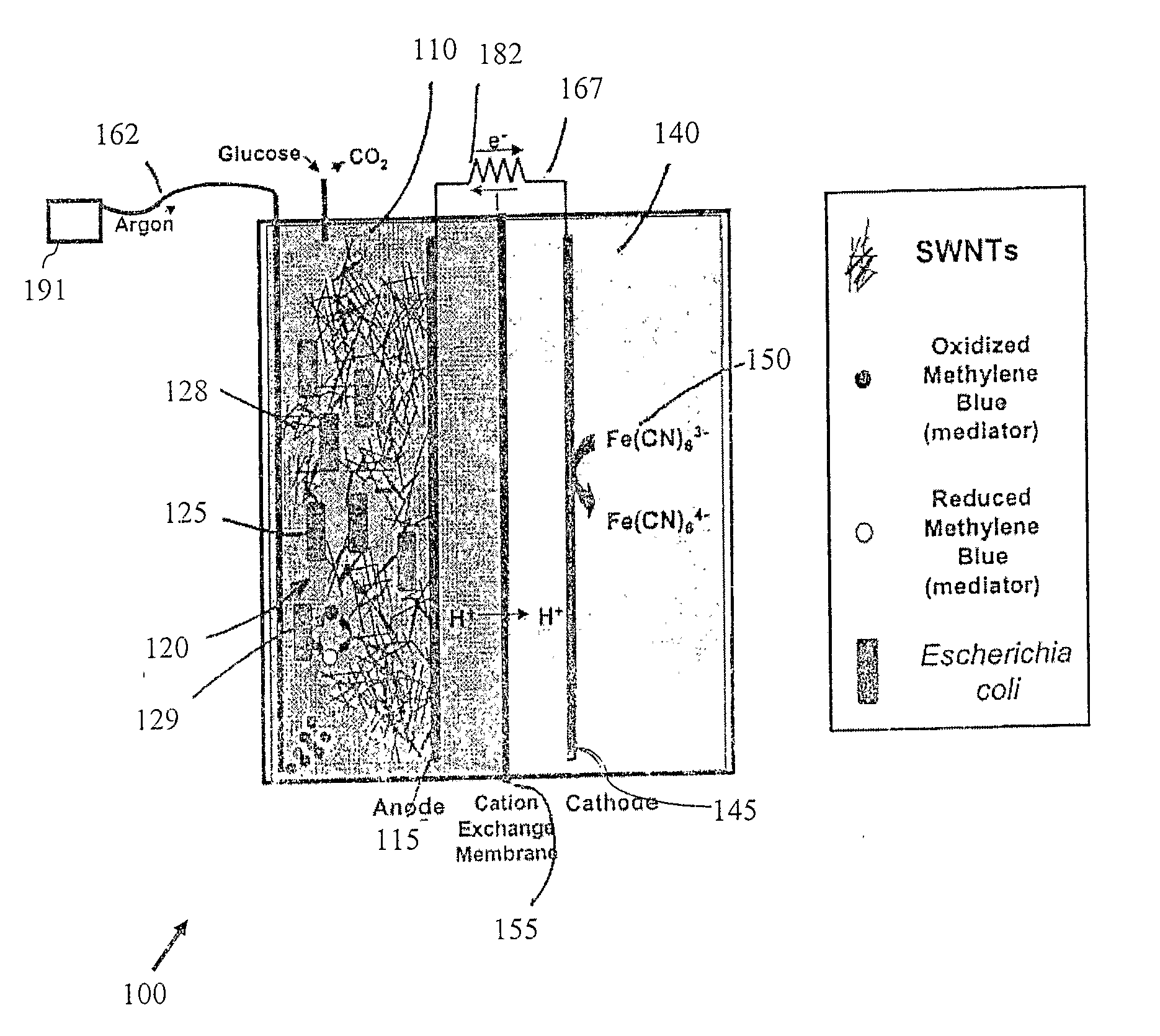
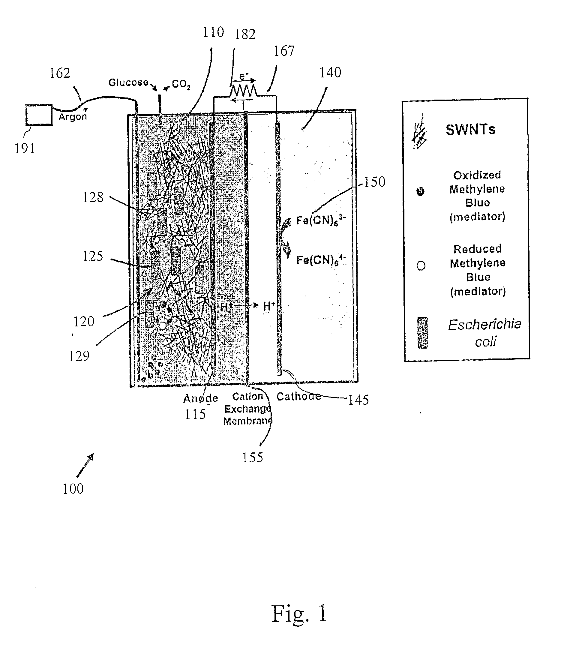
[0008]The catholyte can also comprises a plurality of electrically conducting nano or micro-scale fibers, wherein at least a portion of the plurality of electrically conducting fibers are in electrical contact with a surface of the cathode. The fuel cell can also include a bubbler for bubbling a gas through the anode compartment to increase turbulence therein. A redox mediator can be provided in the anode compartment. The plurality of electrically conducting nano or micro-scale fibers generally form an interconnected network, wherein the network in the anode compartment by virtue of the incidental percolating electrical contact between the fibers allows for growth of new in-vivo cells.

Problems solved by technology

In addition, the anode need not be catalytically active which reduces cost since catalysts such as Pt commonly used as anode catalysts are expensive.
In hydrogen PEM fuel cells, the anode catalyst is in intimate electrical contact with the electrically conductive anode material being typically some form of conductive carbon resulting in low electrical impedance for electron transfer from the catalyst to the anode.
Although microbial fuel cells have shown some promise, the slow transfer rate of electrons to the electrode has significantly limited power output of such fuel cells, and thus their commercial applicability.

Method used


Image

  • Enhanced Electrical Contact to Microbes in Microbial Fuel Cells
  • Enhanced Electrical Contact to Microbes in Microbial Fuel Cells
  • Enhanced Electrical Contact to Microbes in Microbial Fuel Cells

Examples


example 1

[0027]A suspension of single-walled carbon nanotubes (SWNTs) was added to the anode compartment of a two chambered microbial fuel cell (MFC). The fuel cell included Escherichia coli W3110 (ATCC 27325) as the electron donor in the anode compartment and methylene blue was used as the redox mediator.

[0028]The basic MFC assembly (NCBE, The University of Reading, UK) included Perspex (acrylic) chambers, neoprene gaskets, a carbon fiber anode and cathode (cut to 2.4 cm×3.3 cm) and a cation-exchange membrane (Nafion-117). Assembly of these components was performed as disclosed by the supplier and as described by Benetto (1990) Biotechnology Education 1: 163-168. In addition, platinum wire (from Mini-Subcell GT electrophoresis apparatus electrodes, BioRad, Hercules, Calif.) was used to connect the carbon fiber anode and cathode to the external circuit, consisting of a 1000 ohm resistor and an ammeter (46-Range Digital Multimeter with PC interface and data-logging MeterView 1.0 software, Rad...

example 2

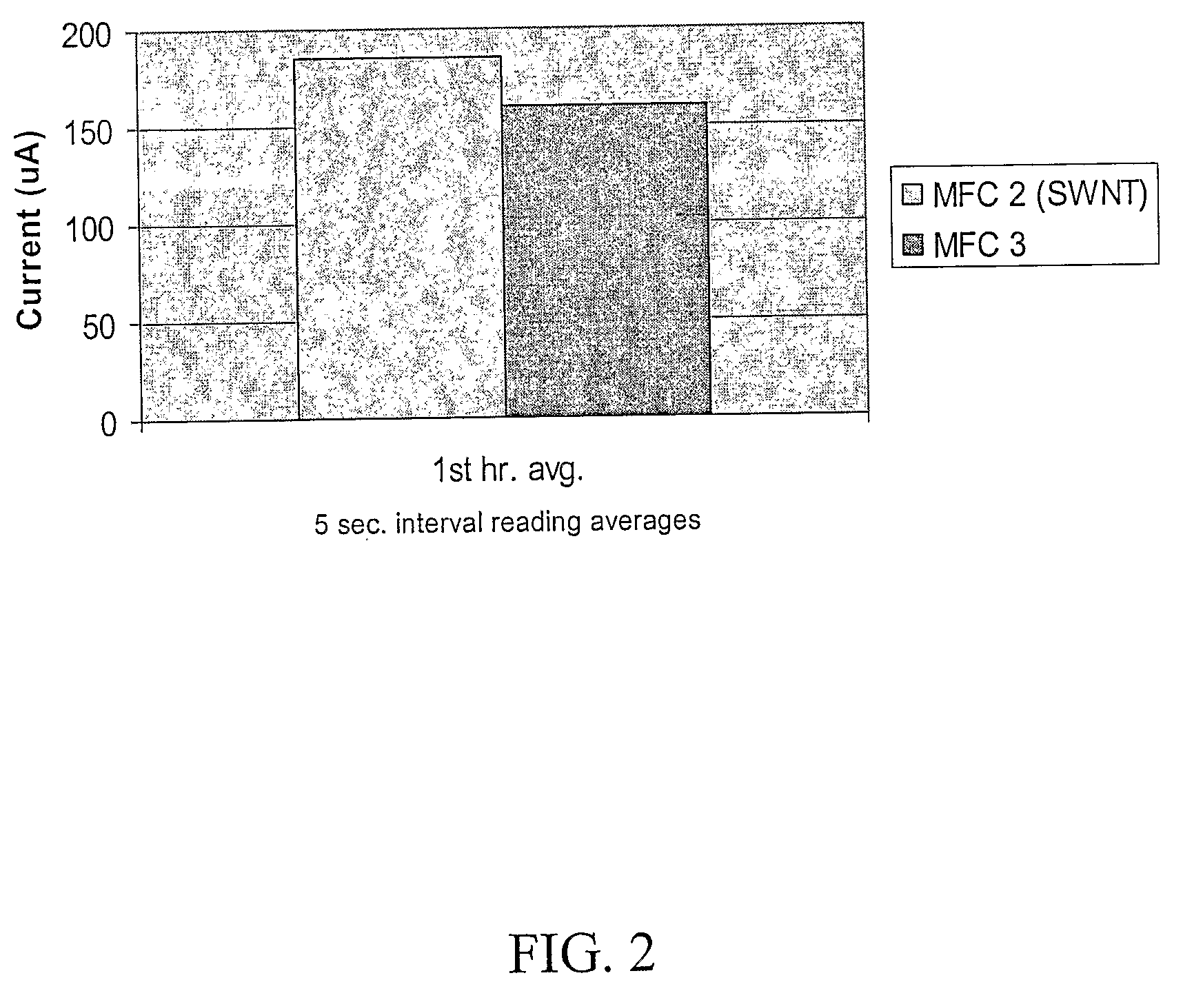
[0035]Microbial fuel cells were set up as before, but a mixed length carbon fiber suspension was used to increase the effective anode surface area and to improve electron transfer efficiency. During the first trial it was found that the mixed carbon fibers could not be transferred by syringe as the SWNTs described in Example 1 were. This necessitated the feeding of the aggregated fibers through the feeding / vent tube in the anode chamber, after the addition of the cell suspension, prior to addition of mediator. This process was performed by pushing the fibers through the tube with toothpicks. Upon addition of all components, the carbon fiber MFC(CF MFC) was observed to produce a current that was nearly twice that of the control MFC as shown in FIG. 5.

[0036]For the second trial with the CF-MFC, the carbon fiber suspension was transferred as several aggregates from which most of the liquid had been removed, to the anode compartment during assembly. Escherichia coli W3110 cells were res...


PUM


Abstract

A microbial fuel cell (100) includes an anode compartment (110) including an anode (115) and anolyte (120). The anolyte (120) comprises a plurality of in-vivo cells (125) mixed with a plurality of electrically conducting nano or micro-scale fibers (128), wherein at least a portion of the plurality of electrically conducting fibers (128) are in electrical contact with a surface of the anode (115). A cathode compartment (140) includes a cathode (145) and a catholyte (150). A cation-exchange membrane (155) is disposed between the anode compartment (110) and the cathode compartment (140).

Description

FIELD OF THE INVENTION[0001]The invention relates to electrochemical cells including microbial fuel cells.BACKGROUND OF THE INVENTION[0002]The basic hydrogen PEM fuel cell consists of two catalyst-loaded electrodes separated by a proton exchange membrane (PEM). Molecular oxygen supplied to the catalytically active cathode is dissociated and reduced to O2− (an energetically favored process). Molecular hydrogen supplied to the anode is dissociated and the hydrogen atoms oxidized to protons (H+), giving Up their electrons to the anode. Those electrons propagate through the external circuit to the cathode, delivering work in the process. The protons generated at the anode meanwhile diffuse through the PEM to combine with the reduced oxygen, producing water and heat as the waste products. Both the anode and cathode (in addition to the requirement that they be electrically conductive) are engineered with specific catalysts, commonly Pt, to facilitate the molecular dissociations and the re...

Claims


Application Information

Patent Timeline
IPC IPC(8): H01M8/16H01M8/02
CPCH01M8/0234H01M8/16Y02E60/527Y10S977/746Y02E60/50
Inventor RINZLER, ANDREW G.INGRAM, LONNIE O'NEALSHANMUGAM, KEELNATHAM T.MOORE, JONATHAN C.WU, ZHUANGCHUN
Owner UNIV OF FLORIDA RES FOUNDATION INC
Learn More