
Enhancement of photocatalytic effect with surface roughness in photocatalytic reactors

Active Publication Date: 2018-02-13
UNIV OF SOUTH FLORIDA
View PDF4 Cites 0 Cited by
  • Summary
  • Abstract
  • Description
  • Claims
  • Application Information

AI Technical Summary

Benefits of technology

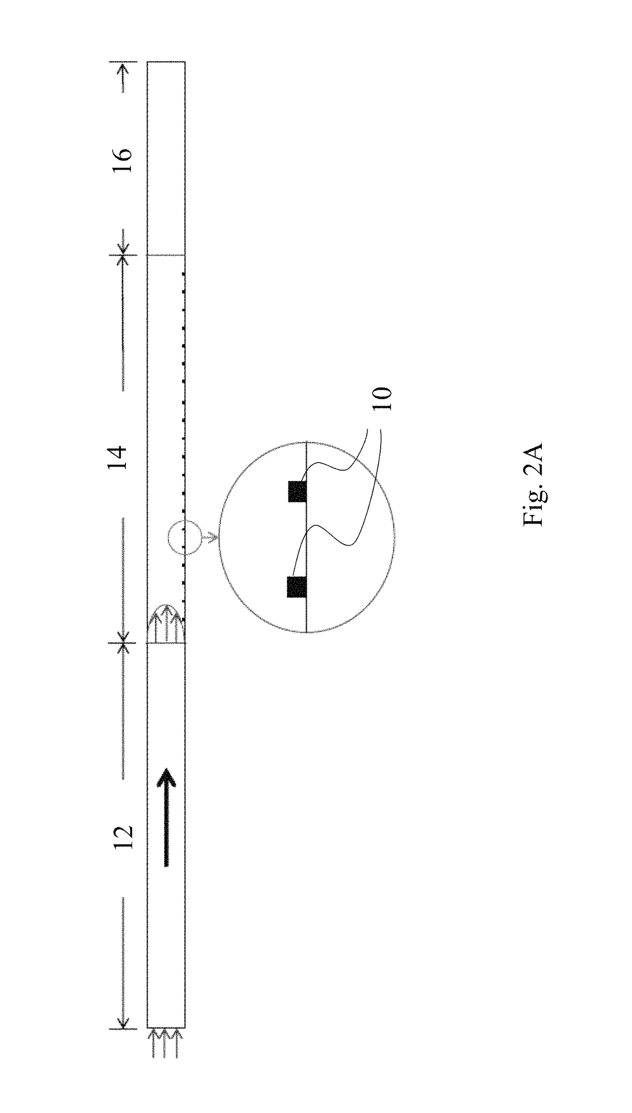
This patent describes a new structure that includes an inlet, reactor section, and outlet section. The reactor section has a rough surface with elements that increase turbulence in the air flow. The roughness elements have a specific shape and size and are positioned on the surface of the reactor catalyst. The reactor is also coated with a photocatalyst coating to improve its efficiency. The technical effect of this patent is an improved reactor design that increases the contact between air and reactor catalyst, leading to better reactor performance.

Problems solved by technology

As the air flows past a catalytic surface, a boundary layer forms along the surface, which does not allow mixing of the air resulting in extremely low probability of contaminant particles coming in contact with the catalytic surface.
When the air flows parallel to a smooth catalytic surface, a laminar sublayer is formed over the surface that impedes the mass transfer of reactants to the catalyst and the reaction products to the main flow, thus adversely affecting the photocatalytic reaction rate.
Although mass transfer plays a significant role in photocatalysis, it has not received much attention in the photocatalytic field.
Although some researchers have started to pay attention to the mass transfer in the kinetic models study, very few have studied how to increase the mass transfer in a photocatalytic reactor.
However, increasing the airflow rate reduces the residence time of the pollutants and leads to incomplete contaminant destruction and more intermediates.
However, Chen and Meng failed to optimize the size, shape, or arrangement of the ribs to match the flow pattern in the reactor channel.
However, the study failed to determine the optimum surface roughness shape and geometry to maximize the effectiveness of photocatalytic air cleaning.
[37] also reported that mass transfer increased greatly with increased turbulence in their experimental investigation.
Although the effect of surface roughness elements in enhancing heat / mass transfer is known, its effect on photocatalytic reactors has not been previously investigated.
Furthermore, where a definition or use of a term in a reference, which is incorporated by reference herein, is inconsistent or contrary to the definition of that term provided herein, the definition of that term provided herein applies and the definition of that term in the reference does not apply.

Method used


Image

  • Enhancement of photocatalytic effect with surface roughness in photocatalytic reactors
  • Enhancement of photocatalytic effect with surface roughness in photocatalytic reactors
  • Enhancement of photocatalytic effect with surface roughness in photocatalytic reactors

Examples


Embodiment Construction

[0043]In the following detailed description of the preferred embodiments, reference is made to the accompanying drawings, which form a part thereof, and within which are shown by way of illustration specific embodiments by which the invention may be practiced. It is to be understood that other embodiments may be utilized and structural changes may be made without departing from the scope of the invention.

[0044]Glossary of Claim Terms

[0045]Catalyst Surface: is the surface of the photocatalytic reactor where the photoreaction takes place.

[0046]Photocatalytic Reactor: is a device capable of acceleration of a photoreaction in the presence of a catalyst.

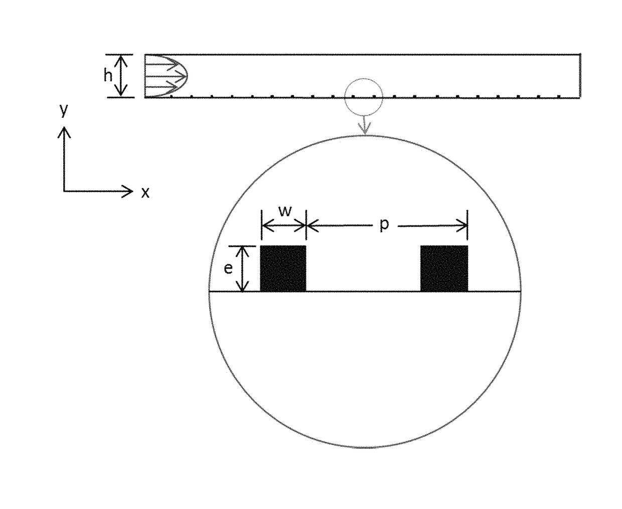
[0047]Roughness Element: is a member extending from a surface that results in the surface not being smooth.

[0048]Relative Height (e / h): is the ratio of height of the roughness element over the height of the duct.

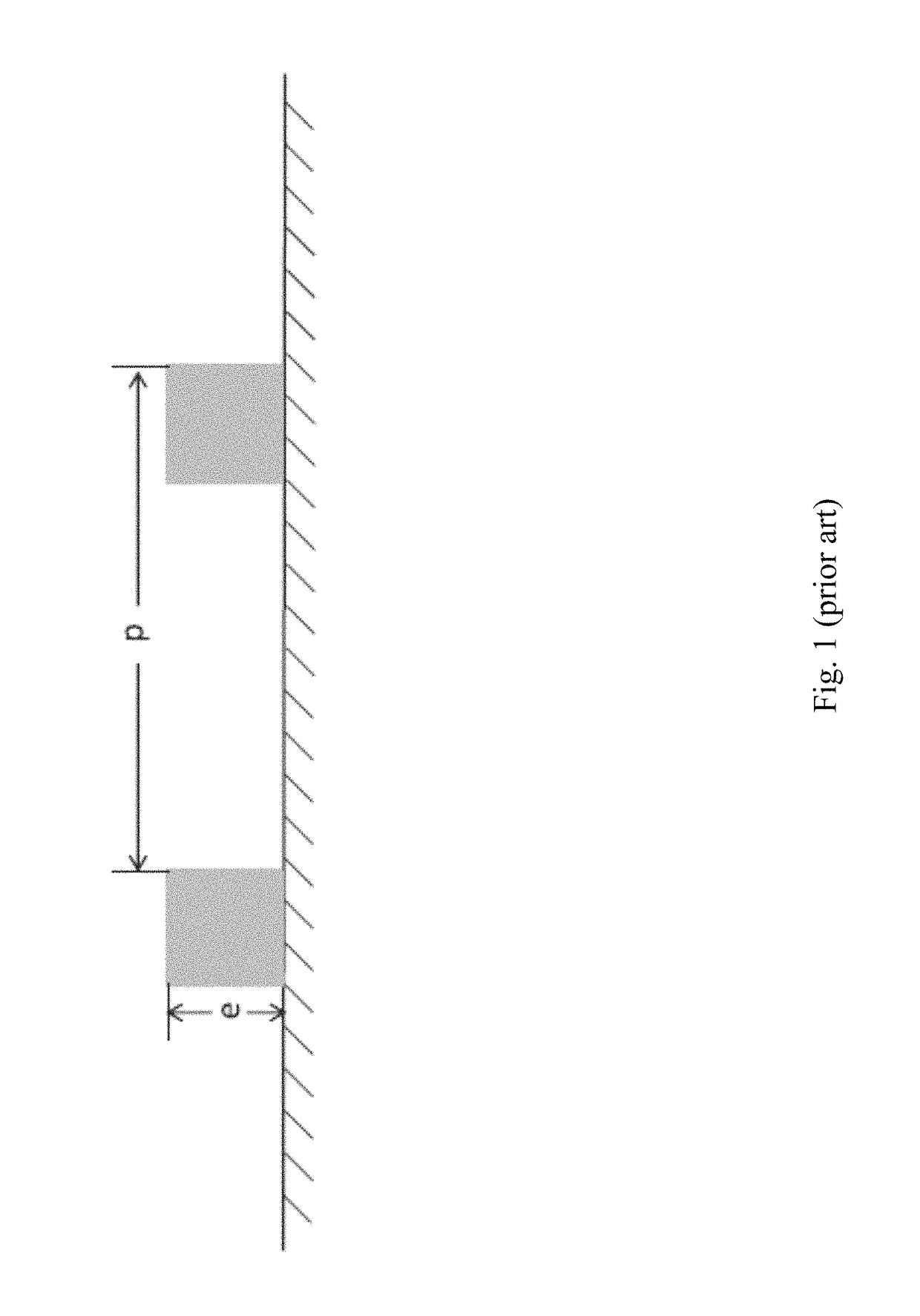
[0049]Pitch Ratio (p / e): is the ratio of the pitch over the height of the roughness element. The pitch is the distance between t...


PUM


Abstract

Photocatalysis is a promising technique for remediation of indoor air pollution. The present invention focuses on the enhancement of the effectiveness of the photocatalytic process by the introduction of artificial roughness on the interior reactor surface. Artificial roughness elements on the catalytic surface enhance the turbulence intensity close to the catalytic surface. The enhanced turbulence intensity translates to an increase in the mass transfer of airborne contaminants to the catalyst surface, improving the efficiency of photocatalysis.

Description

CROSS-REFERENCE TO RELATED APPLICATIONS[0001]This nonprovisional application claims priority to provisional application No. 61 / 889,329, entitled “ENHANCEMENT OF PHOTOCATALYTIC EFFECT WITH SURFACE ROUGHNESS IN PHOTOCATALYTIC REACTORS,” filed Oct. 10, 2013 by the same inventors.BACKGROUND OF THE INVENTION[0002]1. Field of the Invention[0003]This invention relates, generally, to remediation of air pollution. More specifically, it relates to a photocatalytic remediation of indoor air pollution.[0004]2. Brief Description of the Prior Art[0005]Indoor air quality has become a great concern due to the increased time spent indoors.[0006]Most people spend more than 90% of their time in indoor environments such as a home, office, car, shopping center, etc. [1, 2]. Studies show that the level of pollutants indoors is much higher than that of outdoor environments [3, 4]. Photocatalysis is becoming an extremely important method of disinfecting and cleaning indoor air. Photocatalysis is a promisin...

Claims


Application Information

Patent Timeline
IPC IPC(8): A61L9/20F24F1/00F15D1/00
CPCA61L9/205
Inventor GOSWAMI, DHARENDRA YOGISTEFANAKOS, ELIAS K.ZHANG, YANGYANG
Owner UNIV OF SOUTH FLORIDA
Learn More