
Compact reforming reactor

Inactive Publication Date: 2007-01-04
HALDOR TOPSOE AS
View PDF8 Cites 8 Cited by
  • Summary
  • Abstract
  • Description
  • Claims
  • Application Information

AI Technical Summary

Benefits of technology

[0009] It is therefore an object of the invention to provide a reforming reactor with improved temperature distribution across all catalyst tubes.
[0010] It is also an object of the invention to provide a reforming reactor which is compact and free for mechanical means for circulating a heat exchanging medium from the high temperature section of the reactor to the reforming section of the reactor.
[0011] It is a further object of the invention to provide a reforming reactor which is compact whilst at the same time is able to rapidly and simply achieve or maintain its operating temperature after a change in process conditions, such as a change in hydrocarbon feed flow or temperature or a change in burner conditions or during a start-up operation.

Problems solved by technology

Often the heat transfer system in the reforming reactor is not rapid enough to achieve the desired operating temperature after changes in process conditions, such as after sudden load changes or during start-ups and shut-downs, especially when separate heat pipes are provided in the reforming reactor.
Normally a number of more or less sequential steps are required for the start-up of the reforming reactor, resulting in a procedure that may be significantly tedious and time-consuming.
In particular, the provision of a uniform temperature distribution by which all catalyst tubes inside the reactor are heated to the same temperature becomes more difficult to achieve when the heating required in reforming has to be provided by means of a single burner in the reactor.
In addition, the catalyst within the catalyst tubes may often be not evenly distributed so that the catalyst may for instance be better packed in some tubes than others.
This may create undesired variation in temperature conditions across the catalyst tubes.

Method used


Image

  • Compact reforming reactor
  • Compact reforming reactor
  • Compact reforming reactor

Examples


Embodiment Construction

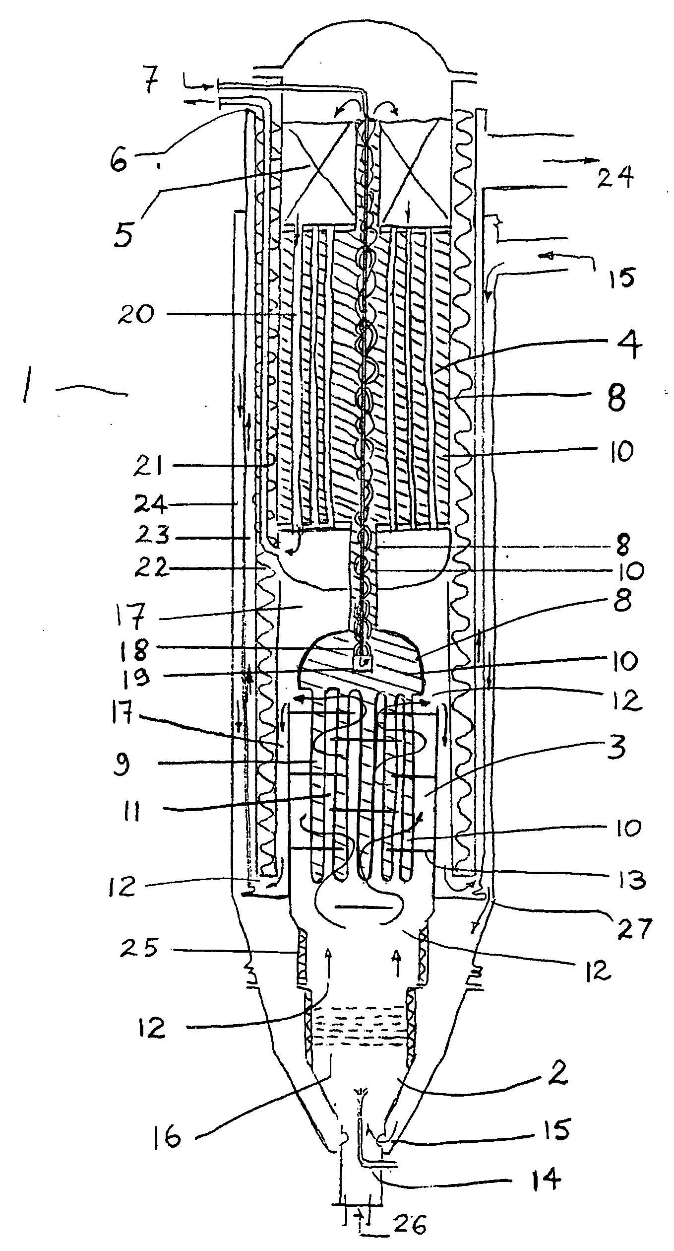
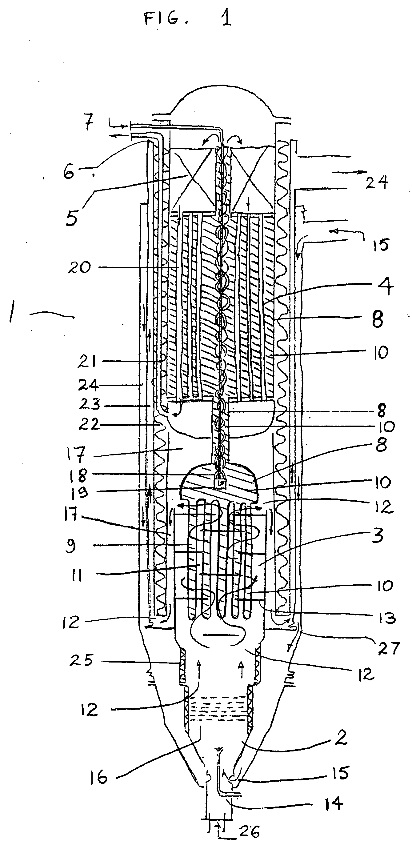
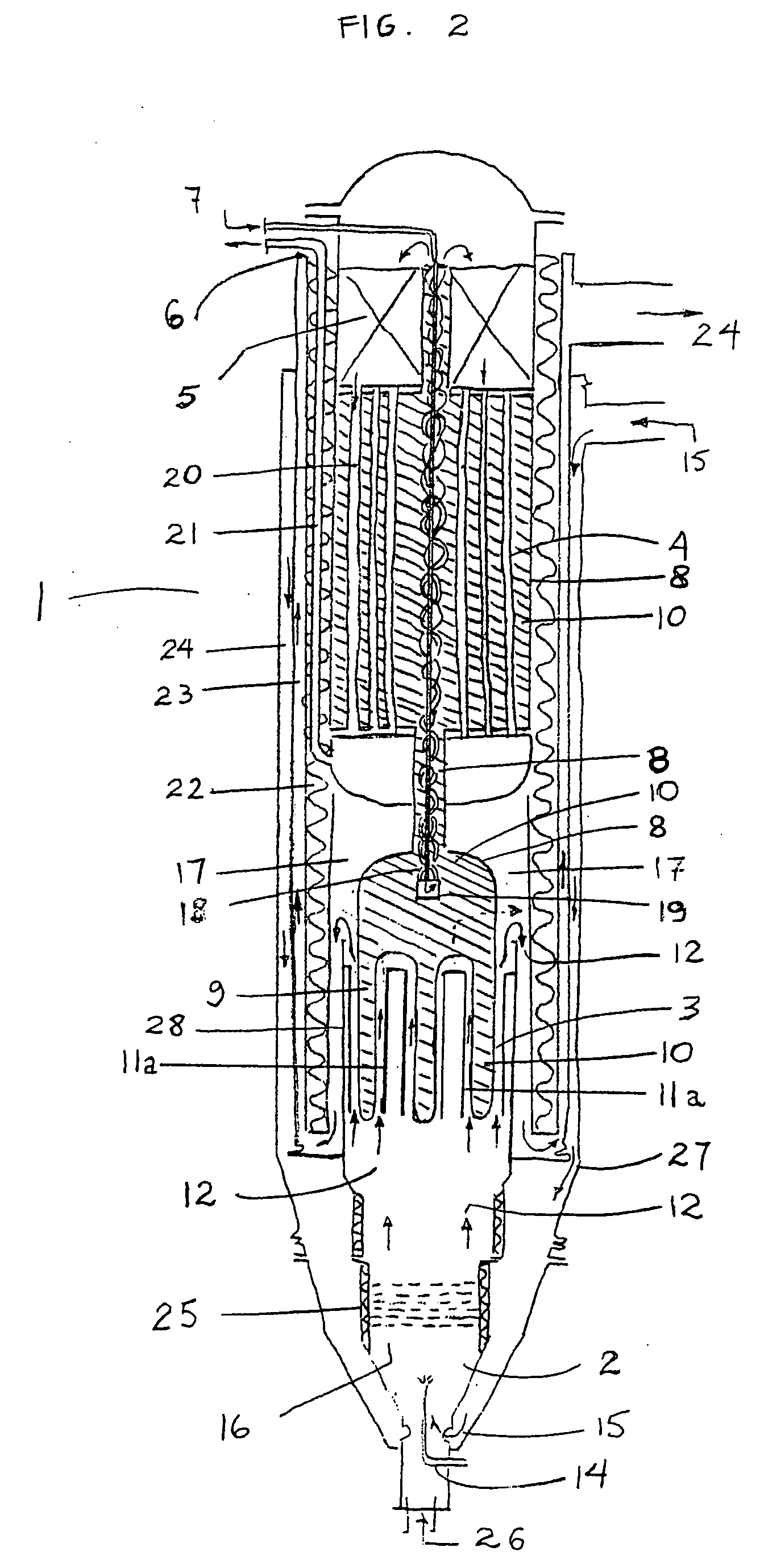
[0072] In FIG. 1 a cylindrical integrated reactor 1 with capacity of 80 Nm3 / h of hydrogen contains a combustion section 2, boiler section 3 and reforming section 4. The cylindrical reactor 1 has a total weight of 300 kg and is about 1.6 m high, with a diameter (except for the combustion section) of about 0.4 m. The total volume of the reactor is about 0.275 m3, while the total catalyst volume is 0.020 m3.

[0073] The reforming section 4 encompasses also a fixed bed of reforming catalyst 5 arranged above the region of the reforming section in which catalyst tubes are disposed. These sections are arranged co-axially in the reactor so as to be able to fit into an outer substantially cylindrical housing.

[0074] A mixture of methanol and water is introduced to reactor 1 through a conduct 6 in the outer wall of the reactor. Through the conduct 6 runs a process feed tube 7 carrying the process fluid (methanol and water mixture). The process tube extends vertically downward to a region insid...


PUM


Abstract

Reforming reactor for the conversion of a process fluid into hydrogen comprising: a reforming section which is contained within a closed volume, a boiler section and a combustion section, in which said reforming section contains one or more catalyst tubes filled with reforming catalyst, said boiler section is provided with one or more flow channels for the passage of flue gas from the combustion section and said combustion section is provided with at least one burner, wherein the heat exchanging medium required for the reforming of said process fluid in the one or more catalyst tubes is a gas-liquid mixture that self-circulates and is encapsulated inside said closed volume and wherein at least a portion of said closed volume protrudes inside said boiler section.

Description

[0001] This is a continuation-in-part of U.S. application Ser. No. 11 / 167,590, filed on Jun. 28, 2005, the entire disclosure of which is incorporated herein by reference.FIELD OF THE INVENTION [0002] This invention relates to an integrated and compact reforming reactor for the production of hydrogen to be used in industrial applications such as in the metallurgical industry, chemical and pharmaceutical industry and fuel cell power plants. In particular the invention relates to a compact reforming reactor for the conversion of hydrocarbon feedstocks to hydrogen where the reformed gas of the reactor is further enriched in hydrogen by passage through a Pressure Adsorption Swing (PSA) unit, a Pd-alloy membrane, water-gas shift unit or by Preferential Oxidation (PROX). More particularly the invention relates to a compact reforming reactor for the conversion of methanol to a hydrogen gas suitable for use in fuel cell plants, especially where the reformed gas of the reactor is further enri...

Claims


Application Information

Patent Timeline
IPC IPC(8): B01J8/00C10J3/46
CPCB01J8/0242F28D15/0266B01J8/0446B01J8/0453B01J8/0469B01J8/048B01J8/0492B01J8/0496B01J8/06B01J8/065B01J8/067B01J19/2495B01J19/26B01J2208/00106B01J2208/00132B01J2208/00185B01J2208/00203B01J2208/00212B01J2208/00221B01J2208/00274B01J2208/00283B01J2208/00309B01J2208/00495B01J2208/00504B01J2208/0053C01B3/384C01B3/505C01B3/56C01B2203/0233C01B2203/0405C01B2203/041C01B2203/043C01B2203/047C01B2203/066C01B2203/0811C01B2203/0822C01B2203/0833C01B2203/0866C01B2203/1217B01J8/0285Y02P20/10C01B3/38C01B3/26F28D15/02
Inventor BOE, MICHAELHANSEN, JOHN BOGILD
Owner HALDOR TOPSOE AS
Learn More