Wide band dispersion-controlled fiber

Inactive Publication Date: 2005-10-11
SAMSUNG ELECTRONICS CO LTD
View PDF21 Cites 3 Cited by
  • Summary
  • Abstract
  • Description
  • Claims
  • Application Information

AI Technical Summary

Benefits of technology

[0012]In accordance with the present invention, the above and other objects can be accomplished by providing a wide band dispersion-controlled fiber comprising a core forming an optical signal transmission path and having a peak refractive index, and a clad surrounding the core and having a peak refractive index lower than the peak refractive index of the cor

Problems solved by technology

If the SMF is used for a long distance transmission, an accumulated dispersion of an optical signal received through the SMF is increased and, as a result, a distortion of the optical signal becomes more severe.
In this regard, there is a problem in

Method used


Image

  • Wide band dispersion-controlled fiber
  • Wide band dispersion-controlled fiber
  • Wide band dispersion-controlled fiber

Examples


first embodiment

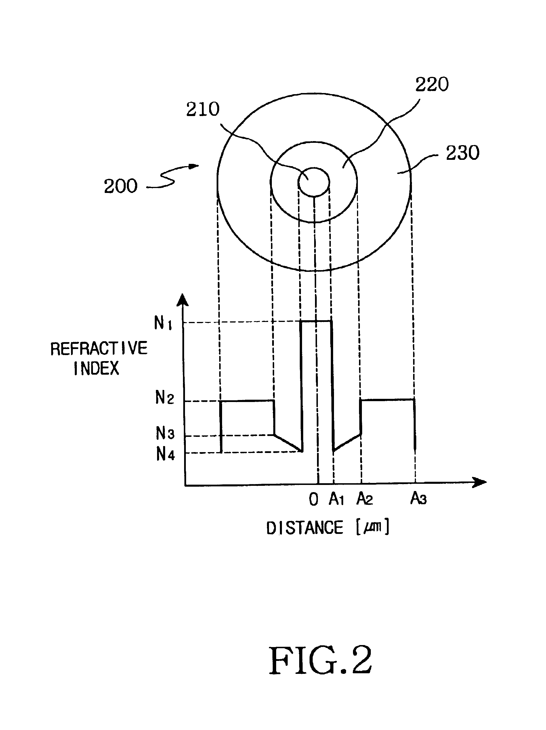
[0023]FIG. 2 illustrates a structure and a respective refractive index profile of a wide band dispersion-controlled fiber in accordance with the present invention. As shown in this drawing, the wide band dispersion-controlled fiber 200 has a core 210, a dispersion-controlled layer 220 and cladding 230.

[0024]The core 210 is arranged in the center of the wide band dispersion-controlled fiber 200 and has a radius of A1 and a refractive index of N1. The core 210 is bar-shaped and has a dispersion profile is set to a constant value N1. A general formula for the refractive index profile is expressed as in the following equation 2. N⁡(R)=N1⁡[1-2⁢Δ1⁡(RA)α1]1 / 2[Equation⁢ ⁢2][0025]where, R(≦A) is a diametrical distance, A(≦A1) a diametrical distance to a certain point within the core 210, N(R) a refractive index according to the R, N1 a peak refractive index of the core 210, Δ1 a first refractive index difference and α1(01≦∞) a first shape index determining a shape of the refractive index pro...

second embodiment

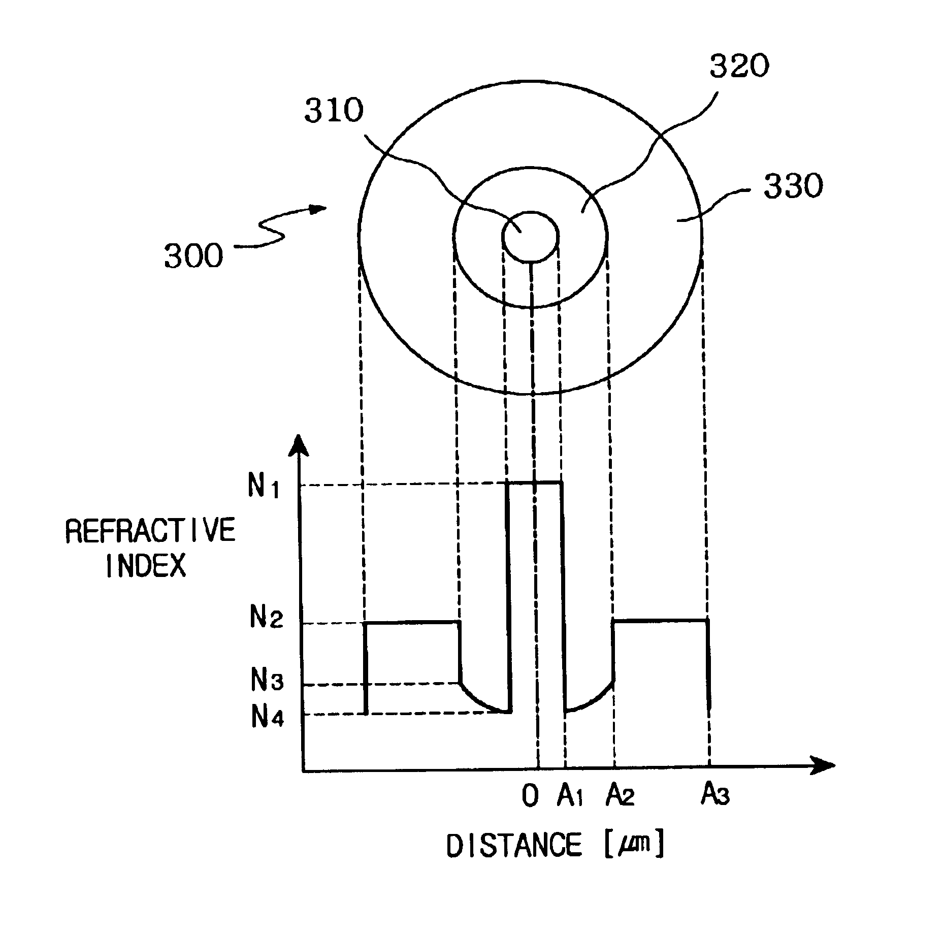
[0033]FIG. 3 illustrates a structure and a respective refractive index profile of a wide band dispersion-controlled fiber in accordance with the present invention. As shown in this drawing, the wide band dispersion-controlled fiber 300 has a core 310, dispersion-controlled layer 320 and cladding 330.

[0034]The core 310 is arranged in the center of the wide band dispersion-controlled fiber 300 and has a radius of A1 and a refractive index of N1. The core 310 is bar-shaped and has a dispersion profile that is set to a constant value N1.

[0035]The dispersion-controlled layer 320 is arranged between the core 310 and cladding 330 and has an inner radius A1, outer radius A3, peak refractive index N3 and minimum refractive index N4. The dispersion-controlled layer 320 further has a tube shape and its refractive index increases curvilinearly from the inner radius to the outer radius.

[0036]The cladding 330 is arranged outside of the wide band dispersion-controlled fiber 300 and has a radius of...

third embodiment

[0037]FIG. 4 illustrates a structure and a respective refractive index profile of a wide band dispersion-controlled fiber in accordance with the present invention. As shown in this drawing, the wide band dispersion-controlled fiber 400 has a core 410, dispersion-controlled layer 420 and cladding 330.

[0038]The core 410 is arranged in the center of the wide band dispersion-controlled fiber 400 and has a radius of A1 and a refractive index of N1. The core 410 further is bar-shaped and its dispersion profile is set to a constant value N1.

[0039]The dispersion-controlled layer 420 is arranged between the core 410 and cladding 430 and has an inner radius A1, an outer radius A3, a peak refractive index N3 and a minimum refractive index N4. The dispersion-controlled layer 420 further has a tube shape and its refractive index increases step-wise from its inner periphery to its outer periphery.

[0040]The cladding 430 is arranged outside of the wide band dispersion-controlled fiber 400 and has a...


PUM


Abstract

A wide band dispersion-controlled fiber which comprises a core forming an optical signal transmission path and having a peak refractive index, and a cladding surrounding the core and having a peak refractive index lower than the peak refractive index of the core. The wide band dispersion-controlled fiber further comprises at least one dispersion control layer arranged between the core and the cladding and having a refractive index profile such that its refractive index increases from an inner periphery to an outer periphery. The minimum refractive index of the dispersion control layer is less than the peak refractive indices of the core and cladding.

Description

PRIORITY[0001]This application claims priority to an application entitled “WIDE BAND DISPERSION-CONTROLLED FIBER”, filed in the Korean Industrial Property Office on Nov. 30, 2001 and assigned Serial No. 2001-75152, the contents of which are hereby incorporated by reference.BACKGROUND OF THE INVENTION[0002]1. Field of the Invention[0003]The present invention relates to an optical fiber. More particularly, the present invention relates to a dispersion-controlled fiber.[0004]2. Description of the Related Art[0005]In general, the dispersion characteristics of an optical fiber can be effectively controlled by positioning a region of a depressed refractive index between a core and a cladding of the fiber. This is disclosed in U.S. Pat. No. 4,715,679 (title: “LOW DISPERSION, LOW-LOSS SINGLE-MODE OPTICAL WAVEGUIDE”) invented by and issued to Venkata A. Bhagavatula, the contents of which are incorporated by reference as background material.[0006]FIG. 1 is a graph illustrating prior art dispe...

Claims


Application Information

Patent Timeline
IPC IPC(8): H04J14/02G02B6/02G02B6/028G02B6/036
CPCG02B6/02261G02B6/0283G02B6/03627G02B6/03688G02B6/028G02B6/02
Inventor CHO, JEONG-SIKDO, MUN-HYUNYANG, JIN-SEONGCHOI, SUNG-WOOK
Owner SAMSUNG ELECTRONICS CO LTD
Why Eureka
Try Eureka