
Method and apparatus for monitoring traffic in a network

a network and traffic monitoring technology, applied in the field of computer networks, can solve the problems of inability to provide complete information to gateways or servers, log file information does not provide a map of real-time usage, and information is simply not available to any gateway or server, and achieve the effect of excessively large pattern databas

Inactive Publication Date: 2005-10-11
PACKET INTELLIGENCE
View PDF93 Cites 104 Cited by
  • Summary
  • Abstract
  • Description
  • Claims
  • Application Information

AI Technical Summary

Benefits of technology

[0023]In its various embodiments the present invention provides a network monitor that can accomplish one or more of the following objects and advantages:
[0027]Be used to help tune the performance of a network according to the current mix of client / server applications requiring network resources.
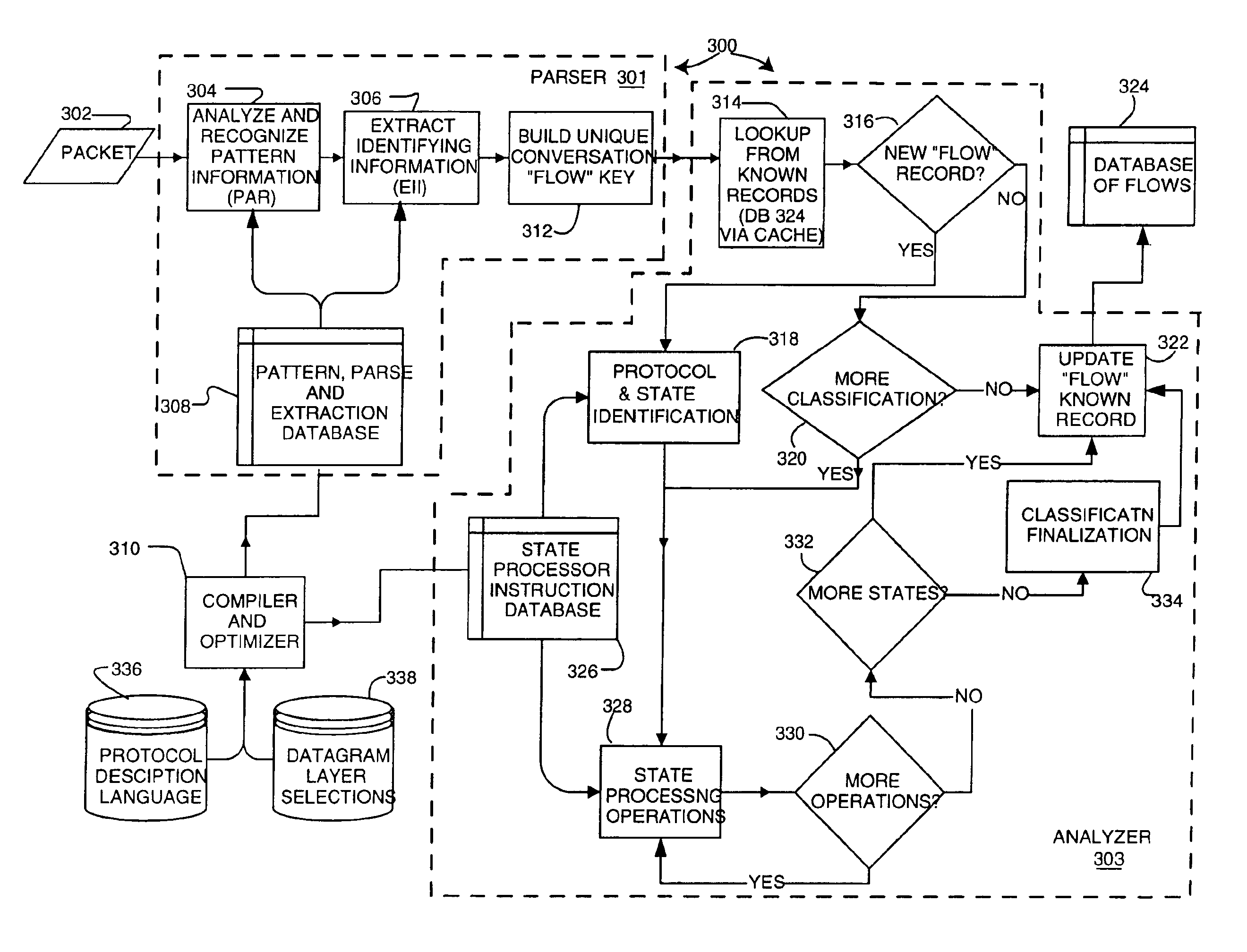
[0043]The pattern database includes a description of the different headers of packets and their contents, and how these relate to the different nodes in a tree. The PRE traverses the tree as far as it can. If a node does not include a link to a deeper level, pattern matching is declared complete. Note that protocols can be the children of several parents. If a unique node was generated for each of the possible parent / child trees, the pattern database might become excessively large. Instead, child nodes are shared among multiple parents, thus compacting the pattern database.

Problems solved by technology

Several problems exist with this method, however.
First, log file information does not provide a map of real-time usage; and secondly, log file mining does not supply complete information.
Also, sometimes information is simply not available to any gateway or server in order to make a log file entry.
Another disadvantage of creating log files is that the process requires data logging features of network elements to be enabled, placing a substantial load on the device, which results in a subsequent decline in network performance.
Additionally, log files can grow rapidly, there is no standard means of storage for them, and they require a significant amount of maintenance.
), RMON2, and other network monitors are available for the real-time monitoring of networks, they lack visibility into application content and are typically limited to providing network layer level information.
Pattern-matching parser techniques wherein a packet is parsed and pattern filters are applied are also known, but these too are limited in how deep into the protocol stack they can examine packets.
With the proliferation of protocols, clearly the specifying of all the possible places to look to determine the session becomes more and more difficult.
Likewise, adding a new protocol or application is difficult.
If a unique node was generated for each of the possible parent / child trees, the pattern database might become excessively large.

Method used


Image

  • Method and apparatus for monitoring traffic in a network
  • Method and apparatus for monitoring traffic in a network
  • Method and apparatus for monitoring traffic in a network

Examples


Embodiment Construction

[0075]Note that this document includes hardware diagrams and descriptions that may include signal names. In most cases, the names are sufficiently descriptive, in other cases however the signal names are not needed to understand the operation and practice of the invention.

Operation in a Network

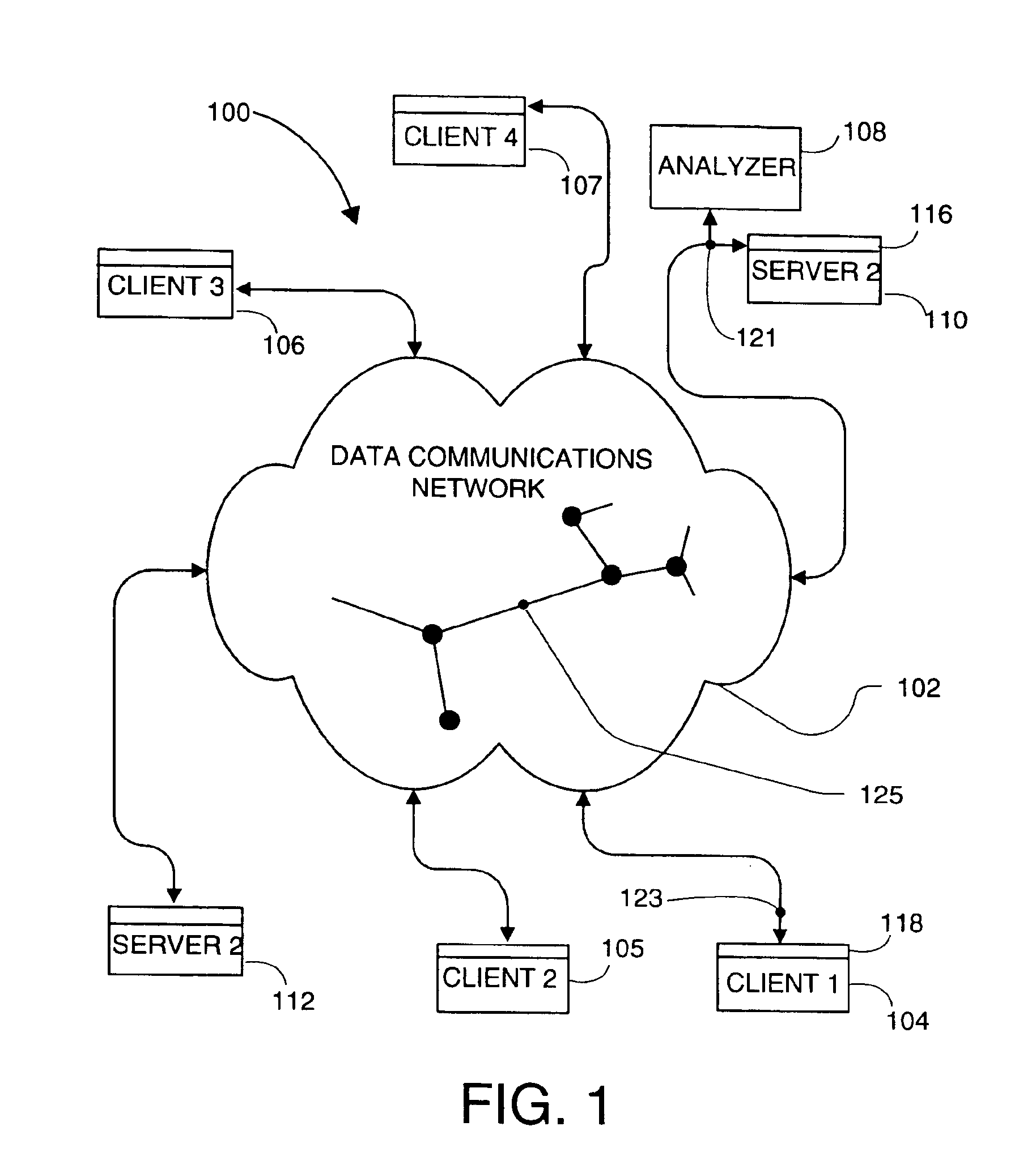
[0076]FIG. 1 represents a system embodiment of the present invention that is referred to herein by the general reference numeral 100. The system 100 has a computer network 102 that communicates packets (e.g., IP datagrams) between various computers, for example between the clients 104-107 and servers 110 and 112. The network is shown schematically as a cloud with several network nodes and links shown in the interior of the cloud. A monitor 108 examines the packets passing in either direction past its connection point 121 and, according to one aspect of the invention, can elucidate what application programs are associated with each packet. The monitor 108 is shown examining packets (i.e., datag...


PUM


Abstract

A monitor for and a method of examining packets passing through a connection point on a computer network. Each packets conforms to one or more protocols. The method includes receiving a packet from a packet acquisition device and performing one or more parsing / extraction operations on the packet to create a parser record comprising a function of selected portions of the packet. The parsing / extraction operations depend on one or more of the protocols to which the packet conforms. The method further includes looking up a flow-entry database containing flow-entries for previously encountered conversational flows. The lookup uses the selected packet portions and determining if the packet is of an existing flow. If the packet is of an existing flow, the method classifies the packet as belonging to the found existing flow, and if the packet is of a new flow, the method stores a new flow-entry for the new flow in the flow-entry database, including identifying information for future packets to be identified with the new flow-entry. For the packet of an existing flow, the method updates the flow-entry of the existing flow. Such updating may include storing one or more statistical measures. Any stage of a flow, state is maintained, and the method performs any state processing for an identified state to further the process of identifying the flow. The method thus examines each and every packet passing through the connection point in real time until the application program associated with the conversational flow is determined.

Description

CROSS-REFERENCE TO RELATED APPLICATION[0001]This invention is a continuation of U.S. patent application Ser. No. 09 / 608,237 for METHOD AND APPARATUS FOR MONITORING TRAFFIC IN A NETWORK to inventors Dietz, et al., filed Jun. 30, 2000, now U.S. Pat. No. 6,651,099, the contents of which are incorporated herein by reference.[0002]This invention claims the benefit of U.S. Provisional Patent Application Ser. No.: 60 / 141,903 for METHOD AND APPARATUS FOR MONITORING TRAFFIC IN A NETWORK to inventors Dietz, et al., filed Jun. 30, 1999, the contents of which are incorporated herein by reference.[0003]This application is related to the following U.S. patent applications, each filed concurrently with the present application, and each assigned to the assignee of the present invention:[0004]U.S. patent application Ser. No. 09 / 609,179 for PROCESSING PROTOCOL SPECIFIC INFORMATION IN PACKETS SPECIFIED BY A PROTOCOL DESCRIPTION LANGUAGE, to inventors Koppenhaver, et al., filed Jun. 30, 2000, now U.S. ...

Claims


Application Information

Patent Timeline
Patent Type & Authority Patents(United States)
IPC IPC(8): H04L12/56H04L12/26H04L29/06H04L12/24G06F13/00G06F17/30H04L69/40
CPCG06F17/30985H04L29/06H04L41/50H04L43/026H04L43/18H04L45/745H04L45/7453H04L47/2441H04L49/205H04L49/3009H04L69/16H04L69/161H04L41/142H04L41/5009H04L43/06H04L43/0817H04L43/0847H04L43/0852H04L43/087H04L43/106H04L43/12H04L49/101H04L49/20H04L49/25H04L49/30H04L49/35H04L69/22H04L69/18Y02B60/33G06F16/90344Y02D30/50H04L9/40
Inventor DIETZ, RUSSELL S.MAIXNER, JOSEPH R.KOPPENHAVER, ANDREW A.BARES, WILLIAM H.SARKISSIAN, HAIG A.TORGERSON, JAMES F.
Owner PACKET INTELLIGENCE
Learn More