Supercharge Your Innovation With Domain-Expert AI Agents!

Peripheral bus switch to maintain continuous peripheral bus interconnect system operation

Inactive Publication Date: 2005-10-11
STORCASE TECH
View PDF16 Cites 12 Cited by
  • Summary
  • Abstract
  • Description
  • Claims
  • Application Information

AI Technical Summary

Benefits of technology

[0010]The first and second peripheral buses to which the arrays of peripheral devices are respectively connected are formed as signal traces over a peripheral bus panel that may include peripheral bus connectors so as to be removably received within a peripheral device enclosure. In this same regard, the peripheral bus switch of this invention can be implemented on a peripheral bus switch circuit board that may include complementary peripheral bus connectors so as to be housed within the same peripheral device enclosure and detachably connected to the signal traces on the peripheral bus panel. Therefore, it will be relatively easy to detachably interconnect the peripheral bus switch between the independent peripheral buses to achieve the fail safe benefits of this invention while minimizing both space consumption within the peripheral device enclosure and the corresponding cost to implement the interconnect system

Problems solved by technology

In the event that one of the first or second peripheral bus controllers should malfunction, it may not be possible to drive the peripheral bus to which the malfunctioning bus controller is connected or to access and use the array of peripheral devices that are associated therewith.
In the event of a failure, the normally functioning peripheral bus controller will fail to receive a timely health check report signal from the malfunctioning controller.

Method used


Image

  • Peripheral bus switch to maintain continuous peripheral bus interconnect system operation
  • Peripheral bus switch to maintain continuous peripheral bus interconnect system operation
  • Peripheral bus switch to maintain continuous peripheral bus interconnect system operation

Examples


Embodiment Construction

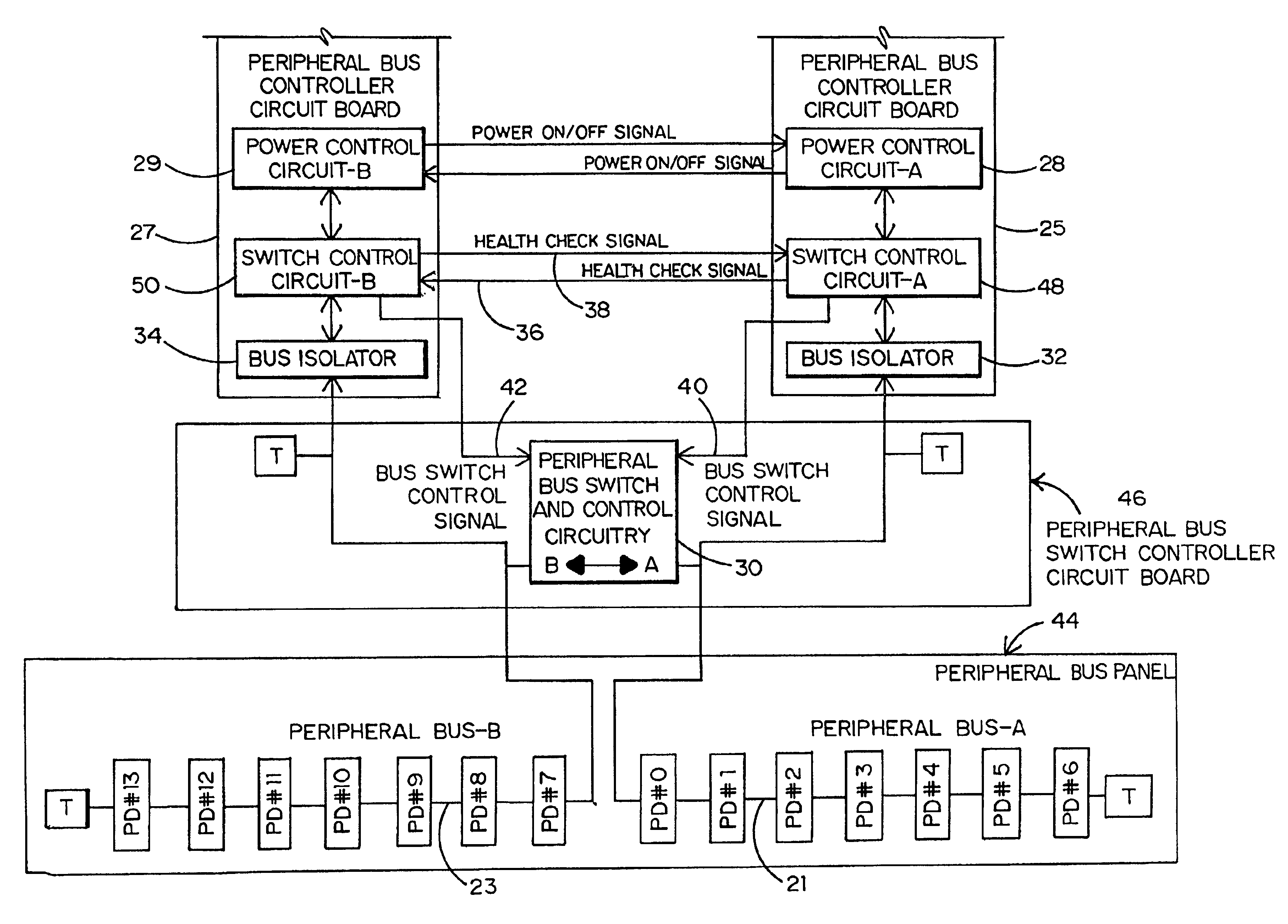
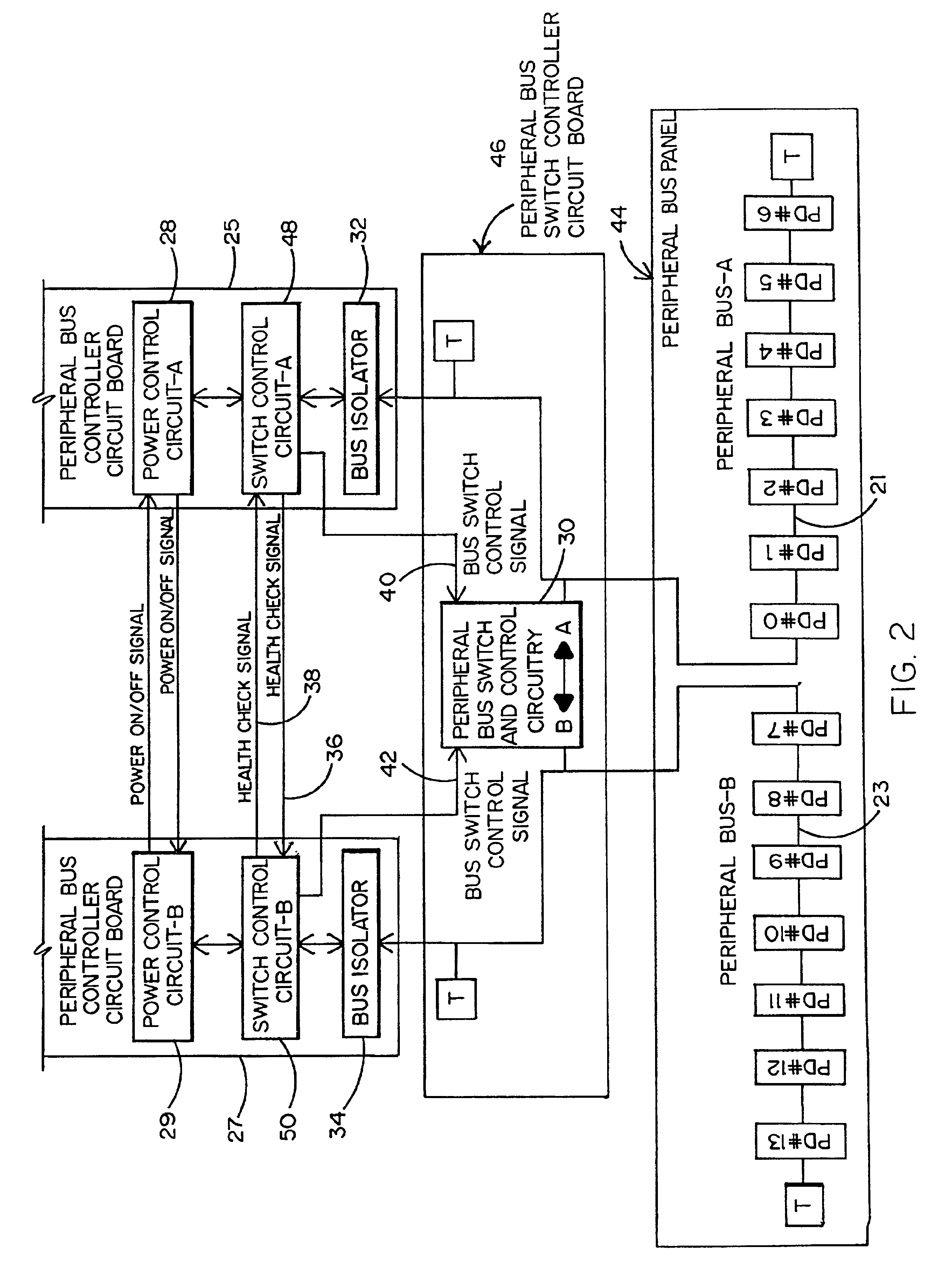
[0013]The high cost and space consumption problems that are inherent by using back-up or redundant peripheral bus controllers in the peripheral bus interconnect system of FIG. 1 are advantageously avoided by the peripheral bus interconnect system shown in FIG. 2 of the drawings. As in the system of FIG. 1, the peripheral bus interconnect system of FIG. 2 includes at least first and second peripheral buses 21 and 23 that are electrically isolated and driven independently from one another. First and second arrays of peripheral devices are respectively connected to the first and second peripheral buses 21 and 23. A pair of terminators (designated T) are located at the opposite ends of each bus 21 and 23 to reduce signal reflections and increase data integrity. Access to and control of the peripheral devices connected to the first peripheral bus 21 is accomplished by means of a first peripheral bus controller 25, and access to and control of the peripheral devices connected to the secon...


PUM


Abstract

A peripheral bus switch that is adapted to connect together a pair of electrically independent peripheral buses to which arrays of peripheral devices (e.g. hard disk drives) are respectively connected in a peripheral bus interconnect system to ensure continuous access to all of the peripheral devices in the event that one of a pair of peripheral bus controllers which drive the peripheral buses should malfunction and require shutdown. The peripheral bus switch is a normally open switch that is connected between the pair of independent peripheral buses. In response to a malfunction, such that one of the pair of peripheral bus controllers fails to generate a timely health check report signal, the properly functioning peripheral bus controller will generate a power down signal to shut down the malfunctioning controller and a bus control signal to cause the normally open peripheral bus switch to close, whereby the properly functioning controller can access the arrays of peripheral devices connected to the pair of peripheral buses without interruption and as if no malfunction had occurred.

Description

BACKGROUND OF THE INVENTION[0001]1.Field of the Invention[0002]This invention relates to a peripheral bus switch that is adapted to connect together a pair of electrically independent peripheral buses to which arrays of peripheral devices are respectively coupled in a peripheral bus interconnect system to ensure continuous and uninterrupted access to all of the peripheral devices in the event that the peripheral bus controller which drives one of the peripheral buses should malfunction and require shut down.[0003]2. Background Art[0004]A conventional peripheral bus interconnect system is described while referring to FIG. 1 of the drawings. In the conventional bus system, at least first and second peripheral buses 1 and 3 are shown to which first and second arrays of peripheral devices (each designated PD0 . . . PD6) are respectively connected. By way of example, such peripheral devices may include a CD drive, a DVD drive, a hard disk drive, and the like. In the case of FIG. 1, each ...

Claims


Application Information

Patent Timeline
IPC IPC(8): G06F13/40
CPCG06F13/4022
Inventor NG, YIU-KEUNG
Owner STORCASE TECH
Features
  • R&D
  • Intellectual Property
  • Life Sciences
  • Materials
  • Tech Scout
  • Unparalleled Data Quality
  • Higher Quality Content
  • 60% Fewer Hallucinations
Learn More