Auxiliary power unit having a continuously variable transmission

a technology of continuously variable transmission and auxiliary power units, which is applied in the direction of road transportation, instruments, gearing, etc., can solve the problems of affecting the heavy duty (, ) sleeper tractor driver, and the speed range of given accessories that cannot operate within the maximum efficiency speed range, so as to minimize the fuel consumption and the minimum fuel consumption value

Inactive Publication Date: 2012-10-11
FALLBROOK INTPROP COMPANY
View PDF3 Cites 121 Cited by
  • Summary
  • Abstract
  • Description
  • Claims
  • Application Information

AI Technical Summary

Benefits of technology

[0017]One more aspect of the disclosure concerns a method for minimizing the fuel consumption of an auxiliary power unit having a continuously variable transmission (CVT). In one embodiment, the method includes the step of providing a computational model (such as the model presented in Equations 1-9 in this document). The method has the step of determining the engine torque and speed as a function of the generator speed and electrical. The method includes the step of performing a regression to determine the fuel consumption rate. In some embodiments, a speed ratio of the CVT is computationally swept from the minimum ratio to the maximum ratio to thereby compute multiple fuel consumption values. For a given generator power demand, the CVT speed ratio can be selected to thereby yield the minimum fuel consumption value. This process can be repeated for increasing electrical power demands to thereby generate a fuel consumption relationship to electrical power demand.

Problems solved by technology

In particular, it has affected the heavy duty (Class 8) sleeper tractor drivers who typically idle their vehicle for many hours each day.
However, it is often the case that the optimum operating speed of the driven device is not directly proportional to the optimum operating speed of the power source.
The result of such system configuration is that often any given accessory does not operate within its maximum efficiency speed range.
Consequently, inefficiencies arise from wasted energy during operation and over sizing of the accessories to handle the speed and / or torque ranges.

Method used


Image

  • Auxiliary power unit having a continuously variable transmission
  • Auxiliary power unit having a continuously variable transmission
  • Auxiliary power unit having a continuously variable transmission

Examples


Embodiment Construction

” one will understand how the features of the system and methods provide several advantages over traditional systems and methods.

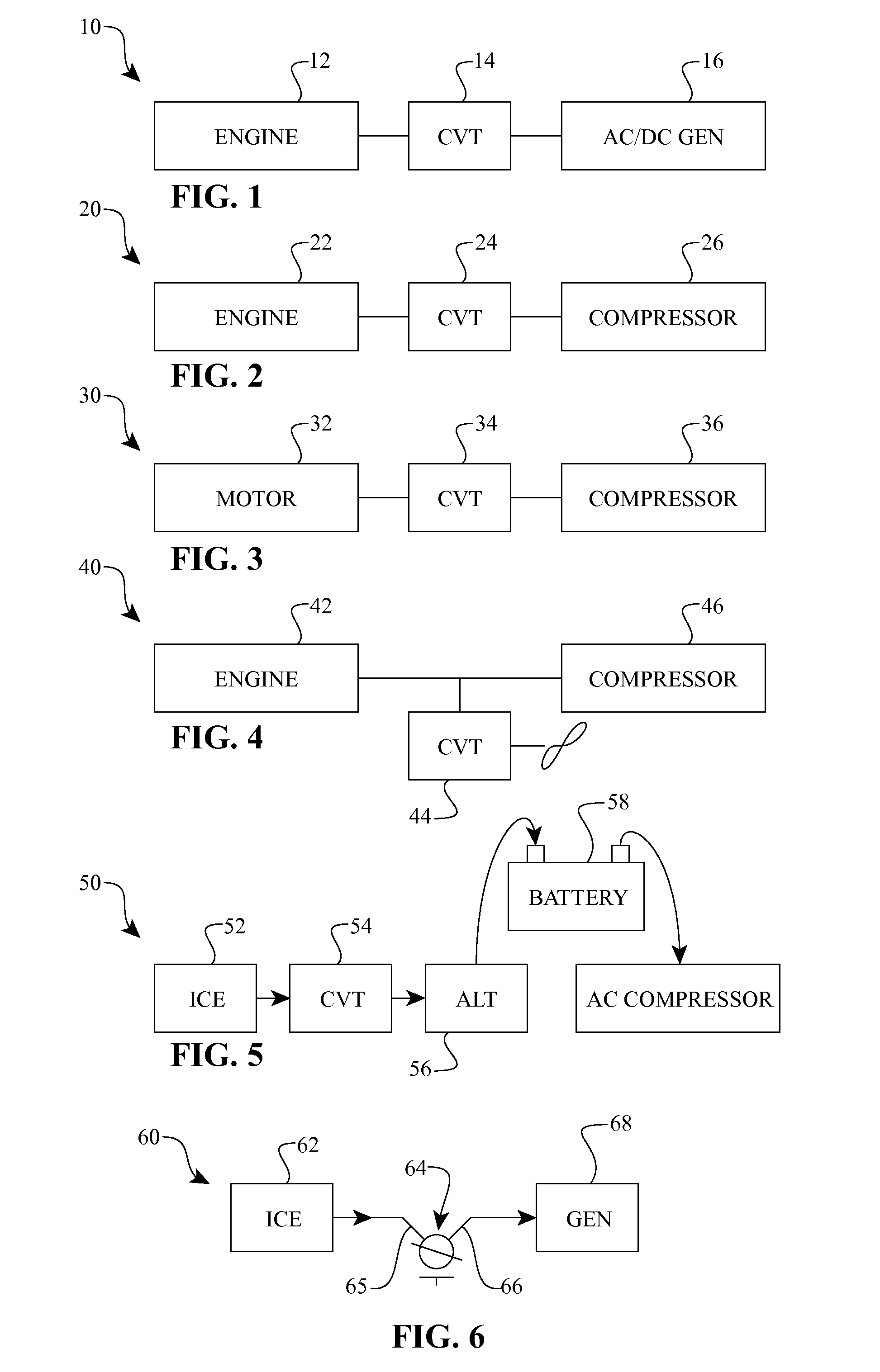
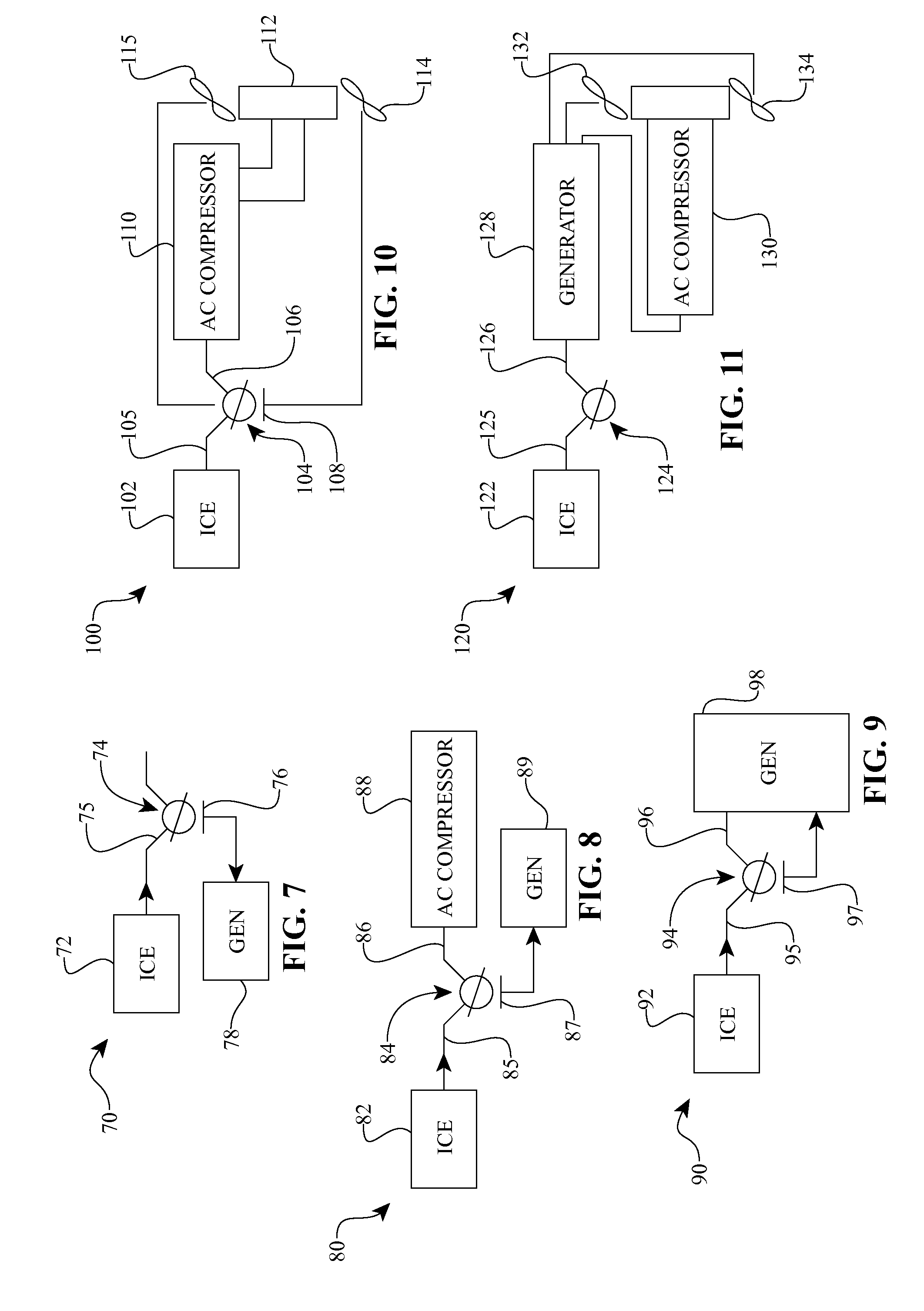
[0012]One aspect of the disclosure relates to a method of controlling an auxiliary power unit having an engine, a generator, and a continuously variable transmission (CVT) coupled to the engine and the generator. In one embodiment, the method includes sensing a change in a load on the generator. The method also includes adjusting the engine to correspond to said change in load and adjusting the speed ratio of the CVT substantially simultaneously with the adjustment of the engine.

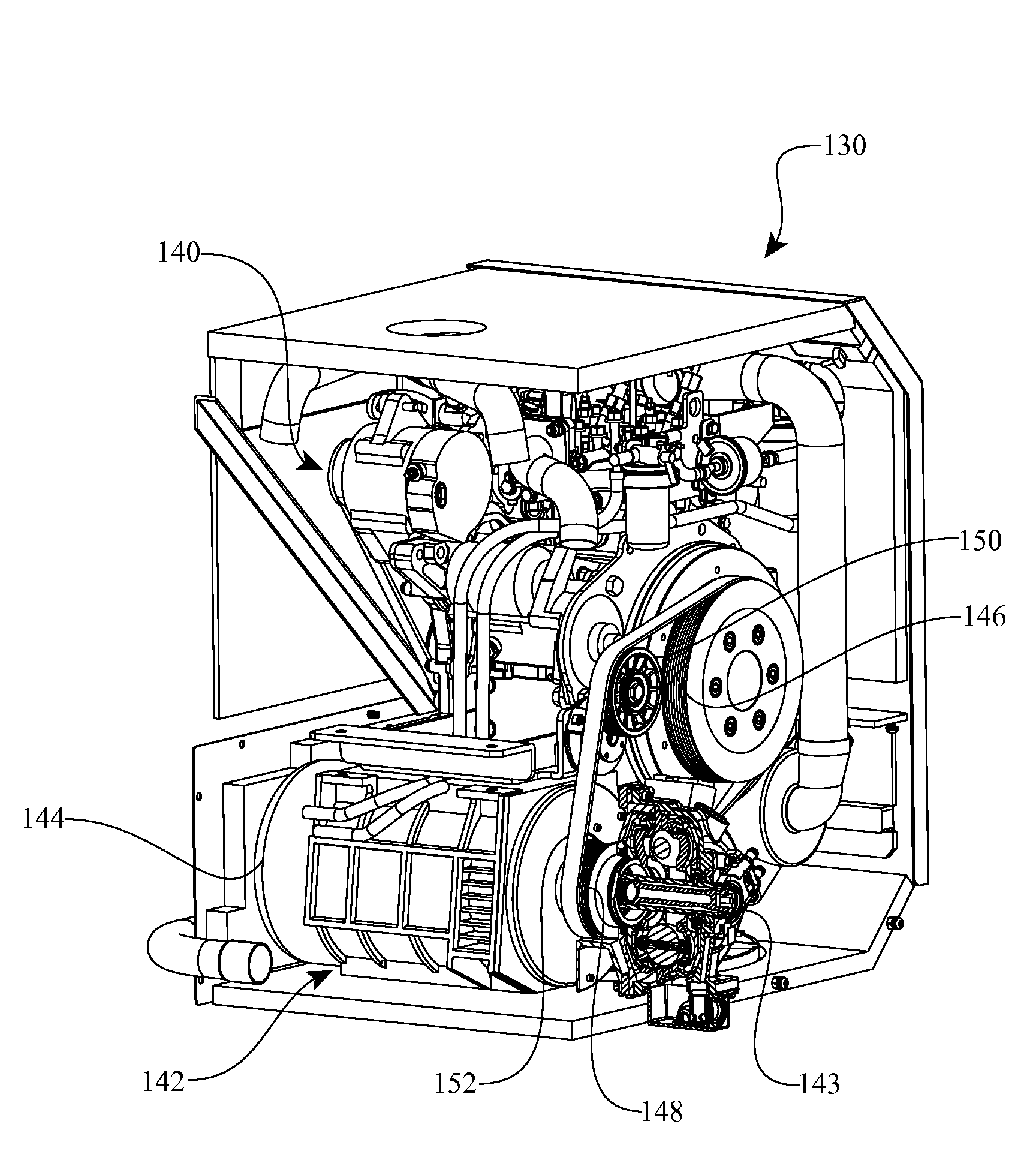
[0013]Another aspect of the disclosure concerns an auxiliary power unit (APU) with a combustion engine having an engine control system adapted to operate the engine at a requested condition. The APU can have a continuously variable transmission (CVT). The CVT has a set of tiltable balls. The CVT is operably coupled to the engine. The CVT has a CVT control system in communication wi...


PUM


Abstract

Inventive embodiments are directed to components, subassemblies, systems, and/or methods for auxiliary power units (APU). In one embodiment, the APU includes a source of rotational power such as a combustion engine operably coupled to a continuously variable transmission (CVT). The CVT can be coupled to a load. In some embodiments, the load is provided by a generator. In one embodiment, the APU has a control system configured to control the operation of the engine and the operation of the CVT. The control system can facilitate substantially constant speed operation of the generator in the presence of variable operation of the engine. In another embodiment, the APU includes a continuously variable accessory drive (CVAD) operably coupled to an engine. The CVAD can include a continuously variable transmission operably coupled to a generator. In one embodiment, a skew-based control system is adapted to facilitate a change in the ratio of a CVAD.

Description

RELATED APPLICATION[0001]This application claims the benefit of U.S. Provisional Application No. 61 / 471,585, filed on Apr. 4, 2011, which is hereby incorporated by reference in its entirety.BACKGROUND[0002]1. Field of the Invention[0003]This disclosure relates generally to mechanical and / or electro-mechanical power modulation devices and methods, and more particularly to continuously and / or infinitely variable, planetary power modulating devices and methods for providing auxiliary air conditioning, heating, and power to a vehicle.[0004]2. Description of the Related Art[0005]Auxiliary power units are often used in cross-country trucks that are equipped with a sleeper compartment located behind a truck cab so that the driver has a convenient place to sleep while in route. An Auxiliary Power Unit (APU) allows the driver to use its truck amenities like heat, air conditioning, microwave, television, etc. without running the engine, which reduces emissions. See, for example, U.S. Pat. No....

Claims


Application Information

Patent Timeline
Patent Type & Authority Applications(United States)
IPC IPC(8): B60W10/101
CPCB60H1/3222B60H1/3226B60K25/02B60W10/06B60W10/101Y10T477/619Y02T10/76F16H61/6648F16H15/42Y10T477/6223B60W30/1886Y02T10/60
Inventor SMITHSON, ROBERTPOHL, BRAD P.LOHR, CHARLES B.SOLIS, JAVIERNIELSEN, TERRYMCBROOM, SCOTT T.MUNGUIA, NICOLE
Owner FALLBROOK INTPROP COMPANY
Why Eureka
Try Eureka