Power slider window assembly

a technology of slider and window assembly, which is applied in the direction of wing accessories, transportation and packaging, wing arrangements, etc., can solve the problems of affecting the appearance of the window assembly, and consuming a large amount of space for drive arrangements, etc., and achieves the effect of quick and easy mounting

Inactive Publication Date: 2005-10-18
MAGNA MIRRORS OF AMERICA INC
View PDF29 Cites 81 Cited by
  • Summary
  • Abstract
  • Description
  • Claims
  • Application Information

AI Technical Summary

Benefits of technology

[0007]Accordingly, a vehicular sliding window assembly of the present invention provides a modular assembly which can be installed in a vehicle, such as a rear cab opening, as a single unit. The window assembly includes one or more sliding window panes which move between open and closed positions. The sliding window panes are preferably driven by a drive assembly which needs only a low power motor to move the respective sliding window panes. At least a portion of the drive assembly is self-contained and supported in a support rail which is mounted to a polymeric member formed around perimeter portions of the fixed window panes. In this manner, the window assembly can be pre-assembled with the drive assembly prior to installation of the window assembly in the vehicle so that window assembly can be quickly and easily mounted during the vehicle assembly process. Furthermore, since at least a portion of the drive assembly is self-contained and supported in the support rail, the drive assembly can be post-attached to the window assembly after the window assembly is installed in the vehicle, which permits retro-fitting of the drive assembly at the dealership.
[0008]In one form of the invention, a vehicular sliding window assembly includes first and second fixed window panes, which are spaced apart to define an opening therebetween. The window assembly further includes at least one guide track and at least one sliding window pane positioned in the guide track. The sliding window pane is positionable along the guide track between an open position and a closed position wherein the sliding window pane closes the opening. A support rail supports the sliding window pane whereby the weight of the sliding window pane is borne by the support rail and not by the guide track to thereby reduce the friction between the sliding window pane and the guide track.
[0013]In one aspect, the support rail supports the first and second sliding window panes above an upwardly facing surface of the lower guide track to reduce the friction between the sliding window panes and the lower guide track. In another aspect, the support rail supports the sliding window panes below a downwardly facing surface of the upper track and above the upwardly facing surface of the lower track to reduce the friction between the sliding window panes and the upper and lower tracks which results a smooth sliding action when the sliding window panes are moved along the upper and lower tracks.
[0021]The present invention provides a modular sliding window assembly that is preferably pre-assembled with a drive assembly thus facilitating handling and installation. In addition, the present invention provides a sliding window assembly that reduces the friction between the sliding panes and the guide tracks, resulting in reduced power requirements for the drive assembly which lowers the cost and the weight of the assembly.

Problems solved by technology

In sliding window assemblies, flush mounting has posed several problems.
Because the electromechanical systems used to move the sliding window panes typically entail complicated drive arrangements and often require large motors to move the sliding panes, these arrangements add significant weight to the window assembly.
Furthermore, these drive arrangements often consume a significant amount of space.
Therefore, for these and various other reasons, these various drive mechanisms have not heretofore been successfully integrated into flush-mounted modular window assemblies.
Another problem with some of the conventional sliding window designs is that the weight of the sliding window panes creates significant friction between the sliding panes and the tracks which are used to support the panes.
This increases the power requirement for the drive mechanism and, hence, the size of the motor.
In addition, the increased friction can result in binding or chattering of the sliding panes which can damage the drive assembly.
In addition, there is a need for a sliding modular window assembly which provides a smooth sliding action of the sliding window panes, which reduces the power requirements of the drive mechanism.

Method used


Image

  • Power slider window assembly
  • Power slider window assembly
  • Power slider window assembly

Examples


Embodiment Construction

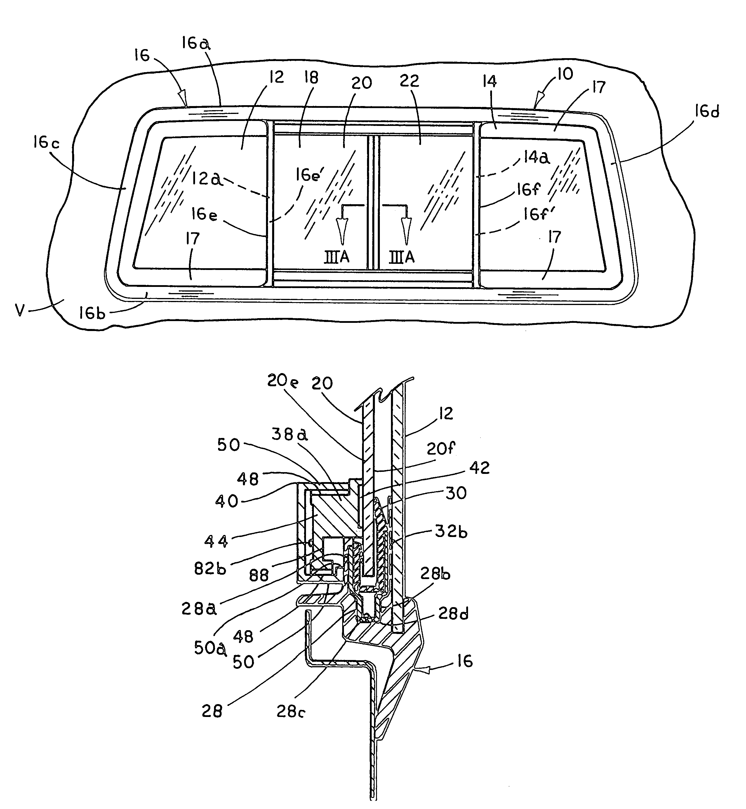
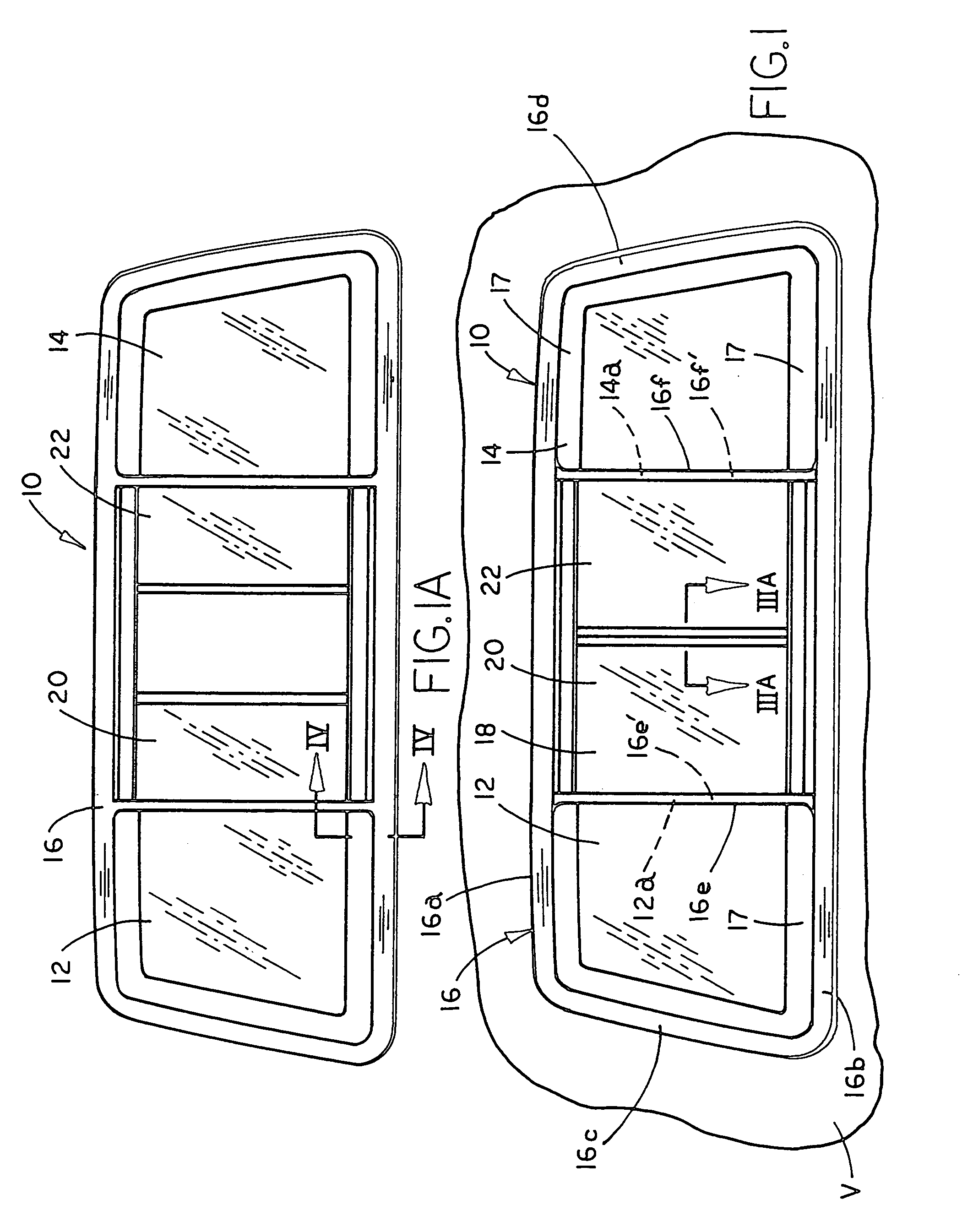
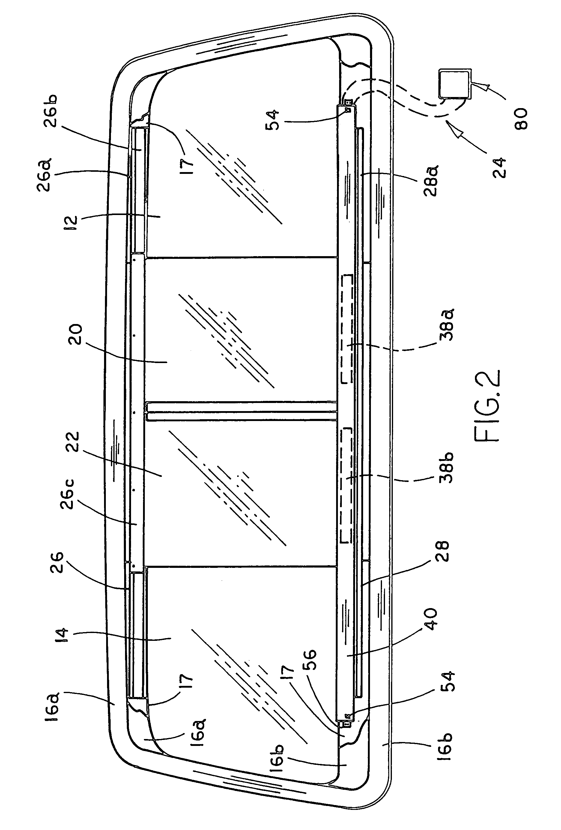
[0045]Referring to FIG. 1, the numeral 10 generally designates a modular sliding window assembly of the present invention. Window assembly 10 is particularly suited for mounting in a rear cab opening of a truck to provide airflow through the cab and, furthermore, to provide access to the bed of the truck. Sliding window assembly 10 is preferably a pre-assembled, self-supporting modular unit which optionally and preferably includes a pre-installed drive assembly 24 (FIG. 2) so that the window assembly can be quickly and easily installed in an assembly line process.

[0046]As shown in FIGS. 1–3, window assembly 10 includes a pair of fixed, spaced apart window panes 12 and 14 and a polymeric member 16, which contacts and spaces fixed panes 12 and 14 to define an opening therebetween. In preferred form, polymeric member 16 is secured to fixed panes 12 and 14 and, more preferably, encapsulated, such as by molding, on at least portions of the perimeters of fixed panes 12 and 14. Preferably,...


PUM


Abstract

A vehicular sliding window assembly of the present invention includes first and second spaced apart fixed window panes and a polymeric member provided on perimeter portions of the fixed window panes. The polymeric member forms a gasket and includes at least one lower guide track molded in the polymeric member. At least one sliding window pane is positioned in the guide track and is positionable between a closed position and at least one open position. The window assembly further includes a support rail, which supports the sliding window pane above a lower surface of the lower guide track whereby the weight of the sliding window pane is borne by the support rail and not the lower guide track to reduce the friction between the guide track and the sliding window pane to provide a smooth sliding action when the sliding window pane is moved along the guide track between its closed and open positions.

Description

[0001]This application is a continuation of U.S. patent application Ser. No. 09 / 638,433, filed Aug. 14, 2000, by Doug Rasmussen entitled POWER SLIDER WINDOW ASSEMBLY, now U.S. Pat. No. 6,591,552, which is herein incorporated by reference in its entirety.TECHNICAL FIELD AND BACKGROUND OF THE INVENTION[0002]Sliding window assemblies are often used, for example, in a rear cab opening of a truck. Typically, such sliding window assemblies include a frame with one or more fixed panes and one or more sliding panes which are either manually operated or operated using electromechanical systems.[0003]The trend in vehicle windows is to form a pre-assembled modular window assembly which can be installed as a single component. In addition, more recently, modular window assemblies are preferably flush mounted, with the window assembly retained by studs or clips that are molded or otherwise attached to the gasket. As a result, the gasket not only provides a seal for the window assembly but now int...

Claims


Application Information

Patent Timeline
Patent Type & Authority Patents(United States)
IPC IPC(8): B60J1/18E05F11/00E05F15/14E05F11/53
CPCB60J1/1853E05F15/643E05F11/535E05Y2900/55
Inventor RASMUSSEN, DOUG
Owner MAGNA MIRRORS OF AMERICA INC
Why Eureka
Try Eureka