Sheet feeder which separates sheets with variable speed and/or direction blown air and image forming apparatus using same

a feeder and variable speed technology, applied in the field of feeders, can solve the problems of surface smoothness, double-feed due to paper-to-paper adhesion rarely occurring, double-feed and/or misfeed, etc., to achieve the effect of reducing the occurrence of sheet-to-sheet adhesion, and reliably eliminating sheet-to-sheet adhesion

Inactive Publication Date: 2005-10-18
CANON KK
View PDF9 Cites 56 Cited by
  • Summary
  • Abstract
  • Description
  • Claims
  • Application Information

AI Technical Summary

Benefits of technology

[0009]Accordingly, it is an object of the present invention to provide a sheet feeder that, in an air sheet feeding method having advantages such as material-adaptability, high-speed paper feeding, high durability, and so on, reliably eliminates sheet-to-sheet adhesion to thereby reduce the occurrence of a misfeed or double-feed by a simple arrangement, and to realize the downsizing of the apparatus, the reduction of the product cost and operational cost, and the improvement in reliability.

Problems solved by technology

To date, in image forming apparatuses such as copying machines and printers, cut sheets serving as recording media that can be continuously fed have usually been limited to high quality paper or to ordinary paper designated by copying machine makers.
Because such paper is low in surface smoothness and air-permeability, air easily enters between sheets, so that, when paper is taken out from stacked paper one by one, a double-feed due to paper-to-paper adhesion rarely occurs.
However, OHP paper, tracing paper, art paper, coated paper, and the like each have high smoothness and air-permeability, and therefore, especially when sheets are stacked in a high moisture environment, double-feed and / or misfeed frequently occurs due to sheet-to-sheet adhesion when using the friction separation method, which has been generally used for conventional copying machines, printers, and the like.
As a result, it has been impossible to inject air into a space between sheets of the lifted sheet bundle, thereby making it very difficult to reliably separate sheets one by one.

Method used


Image

  • Sheet feeder which separates sheets with variable speed and/or direction blown air and image forming apparatus using same
  • Sheet feeder which separates sheets with variable speed and/or direction blown air and image forming apparatus using same
  • Sheet feeder which separates sheets with variable speed and/or direction blown air and image forming apparatus using same

Examples


second embodiment

[0049]A second embodiment according to the present invention will now be described with reference to FIGS. 5A and 5B. In FIGS. 5A and 5B, the same reference numbers are used to denote the same components as those in the first embodiment, and the description thereof are omitted.

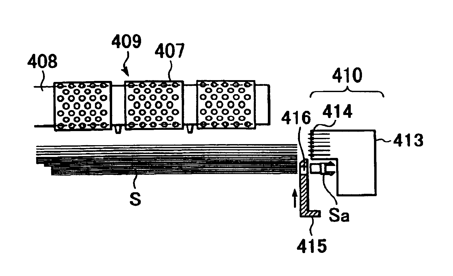
[0050]In this embodiment, a blowing duct 413 and a shutter 415 capable of moving up and down are provided on the front end side of a sheet bundle in the paper feeding direction. A separation duct 418 connected to a separation fan (not shown) has a separation nozzle 419, and it is configured so as to supply separation air in a slanting direction toward the suction belt 407 by the separation nozzle 419. This separation air operates effectively in that it causes only the sheet located in the uppermost position to adhere to the suction belt 407, and separates and lets fall the subsequent sheets.

[0051]In this embodiment, the shutter 415 reciprocates between the uppermost position (FIG. 5A) and the lowermost positio...

third embodiment

[0054]Next, a third embodiment according to the present invention will be described with reference to FIGS. 6A and 6B and FIGS. 7A to 7C. In these figures, the same reference numbers are used to denote the same components as those in the above-described first and second embodiments, and the descriptions thereof are omitted.

[0055]In this embodiment, as shown in FIGS. 6A and 6B and FIGS. 7A to 7C, when the suction belt 407 is driven (i.e., when it is in an on-state), the speed of blown air is set to the vicinity of the minimum speed (see FIG. 7A). The speed of blown air may be varied in accordance with any one of the location of the shutter 415, the magnitude of the blown air supply source, and the cooperation between them. According to this method, paper feed is performed at a timing when the blown air speed is sufficiently low, and therefore, it is possible to provide a sheet feeder that inhibits a double-feed such as to drag the subsequent paper, as described above.

[0056]If, using ...

fourth embodiment

[0058]Next, a fourth embodiment according to the present invention will be described with reference to FIGS. 8A to 8C. In FIGS. 8A to 8C, the same reference numbers are used to denote the same components as those in the above-described first and second embodiments, and the description thereof are omitted.

[0059]In this embodiment, a swing nozzle 421 serving as air direction adjusting means capable of turning the side edge of upper portion of sheet bundle in the up-and-down direction, is provided in the blowing duct 413 disposed on the front end side of the sheet bundle. The swing nozzle 421 continuously blows air on the side edge of the bundle S in an upward direction (see FIG. 8A), substantially in the horizontal direction (see FIG. 8B), and in a downward direction (see FIG. 8C). The swing nozzle 421 blows air while turning in the up-and-down direction, and therefore, with respect to the sheet bundle S, the swing nozzle 421 can give air that continuously varies in air direction, the...


PUM


Abstract

A sheet feeder has a plurality of sheets supported on an intermediate plate, and feeds sheets separately one by one by attracting them by a suction belt. Air is blown from a blowing duct through an opening toward a side edge of a sheet bundle supported by the intermediate plate in order to handle the sheet bundle, and so as to vary the speed and / or direction of air blown from the opening to reliably handle the sheet bundle, whereby a sheet conveying operation by the suction belt is performed when the speed of air blown on the side edge of the sheet located in the uppermost position bundle is not more than a predetermine value.

Description

BACKGROUND OF THE INVENTION[0001]1. Field of the Invention[0002]The present invention relates to a sheet feeder that feeds sheets one by one from a sheet bundle stacked in a sheet storage section.[0003]2. Description of the Related Art[0004]To date, in image forming apparatuses such as copying machines and printers, cut sheets serving as recording media that can be continuously fed have usually been limited to high quality paper or to ordinary paper designated by copying machine makers. Because such paper is low in surface smoothness and air-permeability, air easily enters between sheets, so that, when paper is taken out from stacked paper one by one, a double-feed due to paper-to-paper adhesion rarely occurs.[0005]In recent years, however, with the diversification of recording media, there has been growing requests to form an image on cardboard, OHP paper, and tracing paper, and in addition, on art paper, coated paper, and the like, each of which has a smooth surface and each of wh...

Claims


Application Information

Patent Timeline
Patent Type & Authority Patents(United States)
IPC IPC(8): B65H3/14
CPCB65H3/128B65H3/48B65H2406/41
Inventor KOGA, HIROTO
Owner CANON KK
Why Eureka
Try Eureka