
Expandable interfusion cage

a cage and expansion technology, applied in the field of artificial interfusion implants, can solve the problems of not enabling the use of rigid cages from a posterior direction, small inside volume, and complicating implementation, and achieve the effect of increasing the expansion of the branch part and improving the structural stability of the expanded branch par

Inactive Publication Date: 2005-10-18
KYUNGWON MEDICAL CO
View PDF19 Cites 297 Cited by
  • Summary
  • Abstract
  • Description
  • Claims
  • Application Information

AI Technical Summary

Benefits of technology

[0014]Accordingly, the present invention has been made keeping in mind the above problems occurring in the prior art, and an object of the present invention is to provide an expandable interfusion cage wherein a spacer for expanding a branch part is structured to be moved in an easy manner when it is moved to expand the branch part, structural stability of the expanded branch part is improved, and the expansion of the branch part is increased.

Problems solved by technology

In addition, the inclinations of the facing vertebral faces to which a given angular position is to be imparted do not enable rigid cages to be used from a posterior direction.
However, such devices which are more mechanical than hollow and rigid cages, and therefore more complex, leave a smaller inside volume for the fusion graft, and because of their flat shape which is not circularly symmetrical, even though they are better at ensuring a given bearing angle between the vertebrae, they require a passage of the same rectangular section to be prepared to receive them, which complicates implementation.
The expandable osteosynthesis cage partially solves the defects occurring in the conventional art, but some of the defects still remain.

Method used


Image

  • Expandable interfusion cage
  • Expandable interfusion cage
  • Expandable interfusion cage

Examples


first embodiment

[0036]In the present invention, although it was explained that the cage body has a shape of a hexahedron, a person skilled in the art will readily recognize that the cage body may have a cylindrical or a hexagonal shape while not departing from the scope of the present invention.

[0037]Also, in the first embodiment of the present invention, while it was explained that the branch part 130 comprises four branches 131, a person skilled in the art will readily recognize that the number of branches is not limited to this and instead six or eight branches can be used to constitute the branch part.

[0038]After the expandable interfusion of the present invention is inserted and implanted in an intervertebral space of the spinal column of the human body, powdered bone fills the space between the vertebrae. A powdered-bone leakage prevention door may be provided to prevent the powdered bone from leaking between the vertebrae.

second embodiment

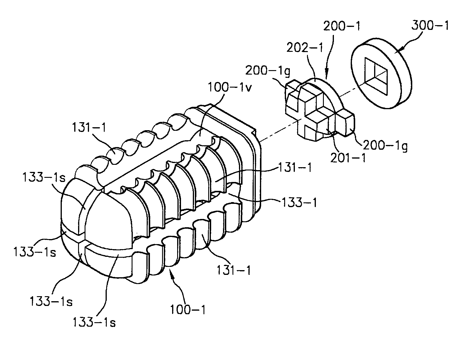
[0039]FIG. 9 is an exploded perspective view illustrating an expandable interfusion cage in accordance with the present invention.

[0040]As shown in FIG. 9, in an expandable interfusion cage in accordance with a second embodiment of the present invention, as in the of the first embodiment, a cage body 100-1 defines therein an inside space 100-1v, and a branch part comprises four elongate branches 131-1. However, the cage body 100-1 of this second embodiment is differentiated from the cage body 100 of the first embodiment in that a guiding slit 133-1s communicated with an opening 133-1 is defined between two adjoining branches 131-1 when viewed on distal end surfaces of the branches 131-1 so that four guiding slits 133-1s cooperate to create a cross-shaped space.

[0041]In this second embodiment of the present invention, a spacer 200-1 comprises a substantially cylindrical spacer body having a head portion 201-1 which is formed as a cross-shaped protrusion of a predetermined size to bia...


PUM


Abstract

An expandable interfusion cage comprising a cage body and a spacer. The cage body includes a seat part which is pierced by an orifice and a branch part which defines therein an inside space and has a plurality of elongate branches integrally formed at their proximal ends with the seat part. An opening is defined between two adjoining branches to communicate with the inside space. The spacer is movably assembled in the inside space of the cage body to expand the cage body radially outward. Inward projections are formed at distal ends, respectively, of the branches to project radially inward toward an axis of the cage body. The inside space of the cage body has substantially a circular or polygonal sectional shape. The spacer is engaged with the inward projections of the branches while expanding the cage body.

Description

BACKGROUND OF THE INVENTION[0001]1. Field of the Invention[0002]The present invention relates, in general, to an artificial interfusion implant installed in an intervertebral space created from the removal of a damaged spinal disk, and more particularly, to an expandable interfusion cage, expandable to increase in diameter.[0003]2. Description of the Prior Art[0004]In order to stabilize, for extended periods, fractures of a damaged spinal disk in humans, a fusion can be implemented, in which at least two bones of the spinal column are connected with each other by a bony bridge. In implementing interbody fusion as well known to those skilled in the art, so as to restore a normal spatial relationship, a spinal disk is partially cut, and a bone segment is positioned between adjacent vertebrae in a space already occupied by a disk material, to provide immediate stability through mechanical support. Also, by subsequent permanent cross-conjugation of vertebral bones, long-term stability i...

Claims


Application Information

Patent Timeline
Patent Type & Authority Patents(United States)
IPC IPC(8): A61F2/44A61F2/30
CPCA61F2/446A61F2/447A61F2/30744A61F2002/30579A61F2002/30777A61F2002/30785A61F2002/30892A61F2002/4475A61F2002/30593
Inventor CHAE, SOO-KYUNGYOUN, JAE-RYOUNYOON, DO-HEUMCHO, YONG-EUNKIM, SANG-TAEKPARK, HYUNG-SANG
Owner KYUNGWON MEDICAL CO
Learn More