Filter frame and assembly

a filter frame and assembly technology, applied in the direction of filtration separation, auxillary pretreatment, separation process, etc., can solve the problems of difficult to carry and position the filter array for installation, the handle is not useful for moving or installing the filter, and the filter media is usually damaged

Active Publication Date: 2005-10-18
FILTRATION GROUP
View PDF26 Cites 62 Cited by
  • Summary
  • Abstract
  • Description
  • Claims
  • Application Information

AI Technical Summary

Problems solved by technology

One disadvantage of the above and other prior art designs is that because of the size of the filter assemblies/arrays often used in large commercial or industrial applications, the filter a

Method used


Image

  • Filter frame and assembly
  • Filter frame and assembly
  • Filter frame and assembly

Examples


Embodiment Construction

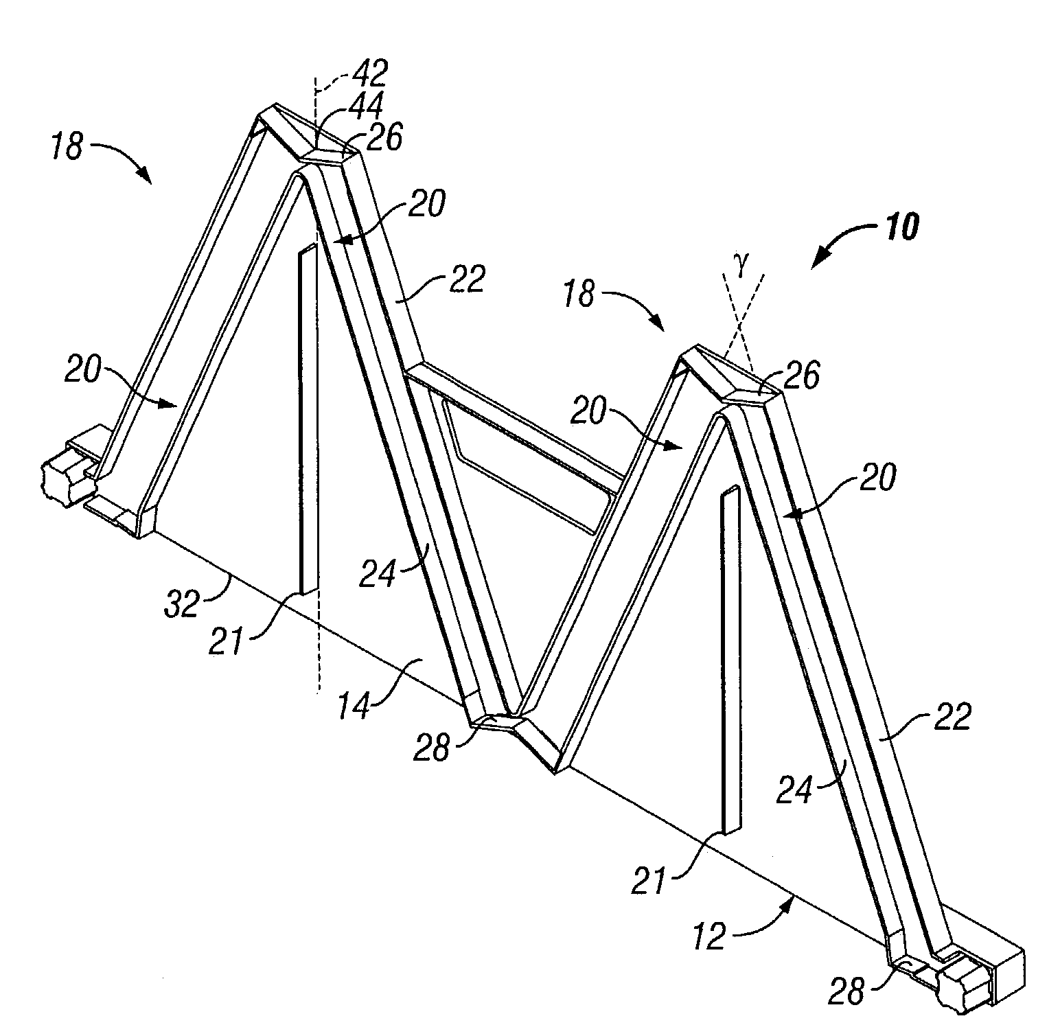
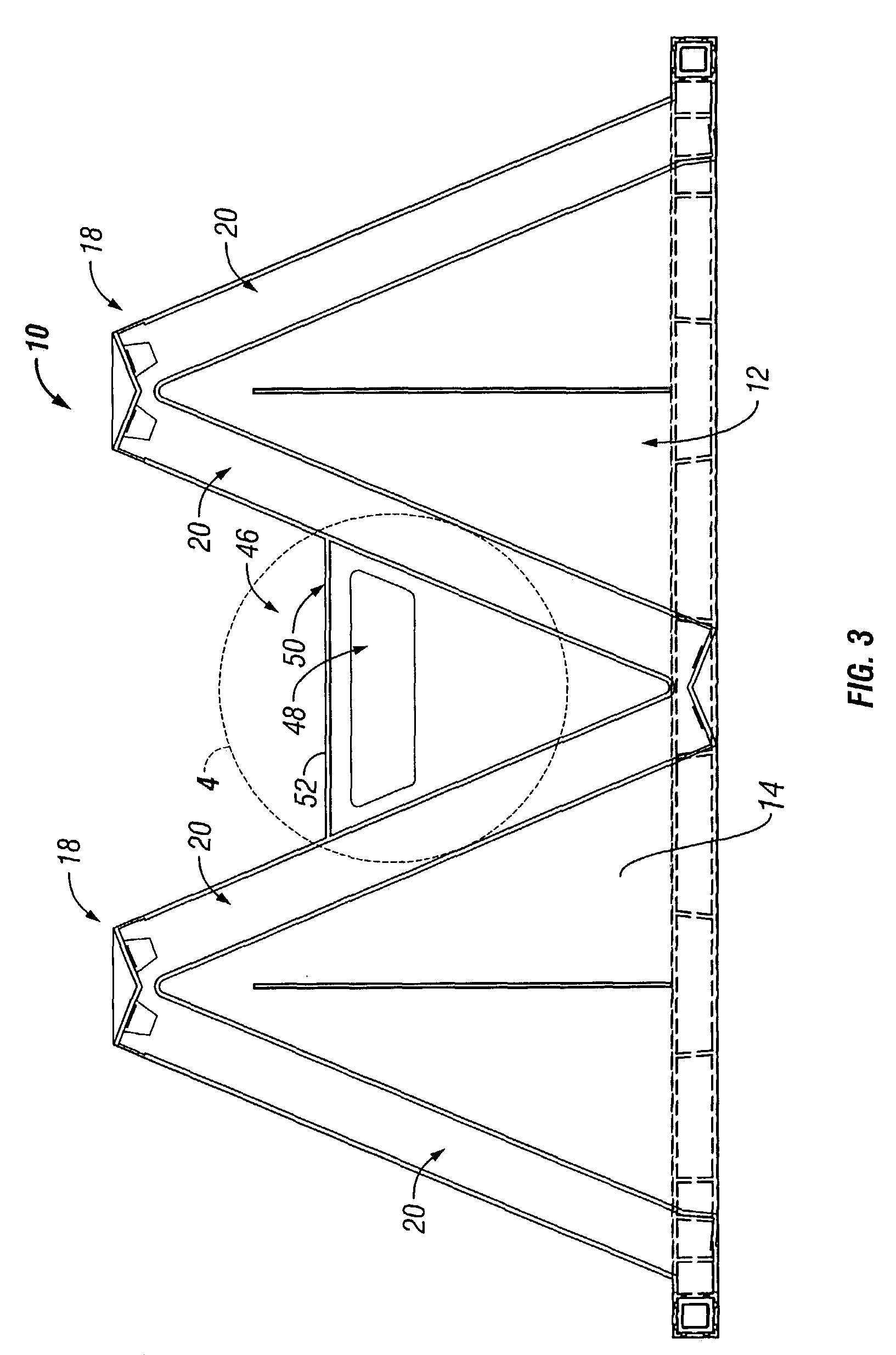
[0013]The filter frame assembly of the present invention is primarily for use in air filtration systems. In one principal aspect of the present invention, a filter frame includes a panel including a plurality of V-shaped elements disposed on a first side of the panel. Each V-shaped element includes a pair of slots. The slots are each configured to receive and orient a filter element. A portion of the panel disposed between adjacent pairs of V-shaped elements has an opening formed therein to define a handle for carrying the filter frame.

[0014]In one embodiment, a rib is disposed on the first side of the panel between the slots of each V-shaped element extending along the line passing through a vertex of the V-shaped element and normal to a base of the panel for reinforcing the panel. In another embodiment, a rail is disposed on a second side of the panel at a base thereof having an extent greater than the base. In still another embodiment, a connector is disposed at each end of the r...


PUM

PropertyMeasurementUnit
Angleaaaaaaaaaa
Areaaaaaaaaaaa

Abstract

A filter frame including a panel having a plurality of V-shaped elements disposed on the first side thereof. Each V-shaped element includes a pair of slots each configured to receive and orient a filter element. A portion of the panel disposed between adjacent pairs of V-shaped elements has an opening form therein to define a handle for carrying the filter frame.

Description

BACKGROUND OF THE INVENTION[0001]The invention relates generally to filter element supports, and in particular to a filter frame assembly for supporting a plurality of filter elements and including a handle for carrying.[0002]Prior art filter assemblies are known. For example, U.S. Pat. No. 4,193,780, issued to Cotton, Jr. et al., describes a plurality of separate V-shaped wire mesh members arranged and connected in side-by-side relationship to provide a plurality of V-shaped cells disposed across an air stream. A stabilizer bar extends across and attaches to the exposed edges of the V-shaped cells to support the cells in a proper relation and retain the filter media in place. Additionally, the stabilizer bar stabilizes the frames to decrease vibration and rattle when the system is operating. No handle is provided for carrying the filter assembly.[0003]U.S. Pat. No. 2,016,033, issued to Christofferson, describes an air filter, which has filter media disposed between a pair of V-shap...

Claims


Application Information

Patent Timeline
IPC IPC(8): B01D46/10B01D29/07B01D29/01B01D46/00B01D46/12B01D46/42
CPCB01D46/0005B01D46/002B01D46/10B01D46/125B01D46/42B01D2265/024Y10S55/31B01D46/58B01D46/121
Inventor OST, LAWRENCE H.OST, BRANDON H.BECK, HERSHEL E.WINTERS, PHILIP J.
Owner FILTRATION GROUP
Why Eureka
Try Eureka