Compaction managed mirror bend achromat

a technology of mirror bend achromat and compaction management, which is applied in the direction of magnetic discharge control, discharge tube/lamp details, instruments, etc., can solve the problem of limited effect of mba

Active Publication Date: 2005-10-18
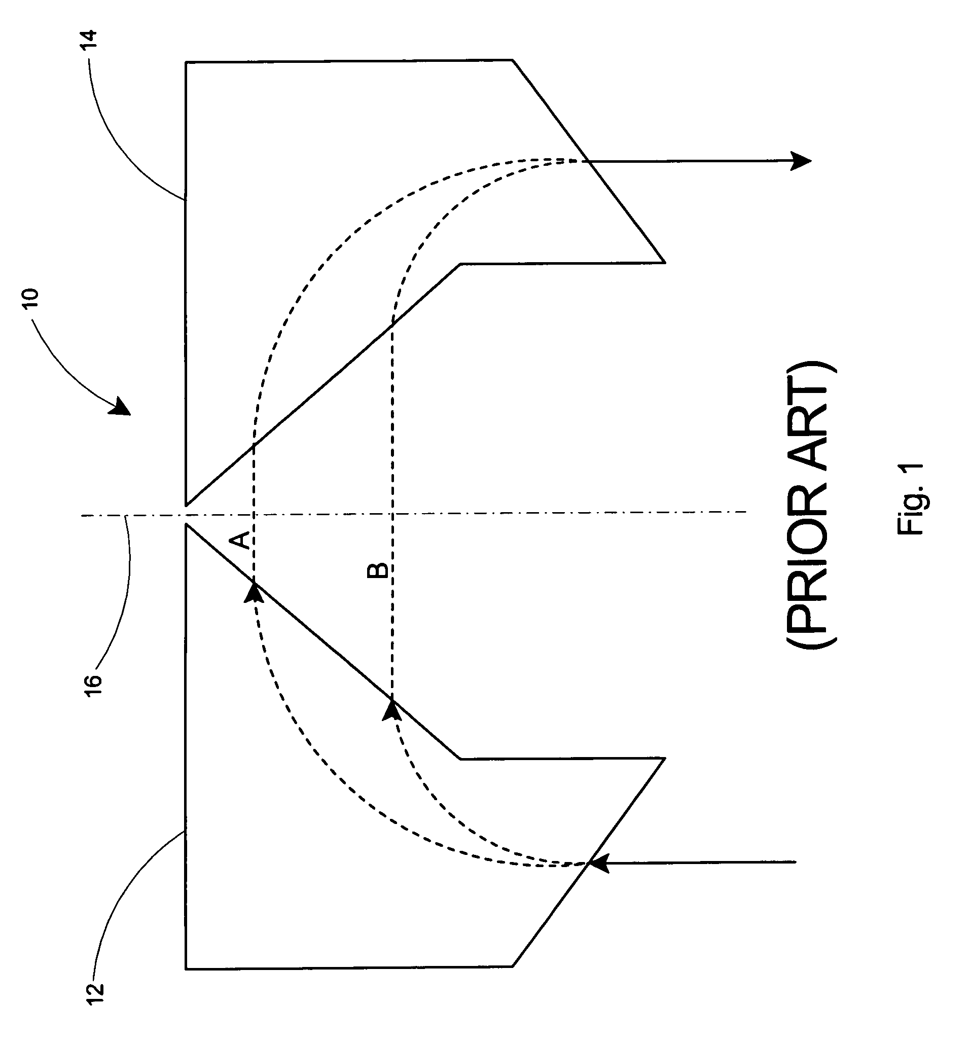
JEFFERSON SCI ASSOCS LLC +1
View PDF2 Cites 3 Cited by
  • Summary
  • Abstract
  • Description
  • Claims
  • Application Information

AI Technical Summary

Benefits of technology

[0005]What is needed for compact ERLs and similar particle accelerators is a design methodology freeing t

Problems solved by technology

The effectiveness of the MBA is, however, limited by the restricted range

Method used


Image

  • Compaction managed mirror bend achromat
  • Compaction managed mirror bend achromat
  • Compaction managed mirror bend achromat

Examples


examples

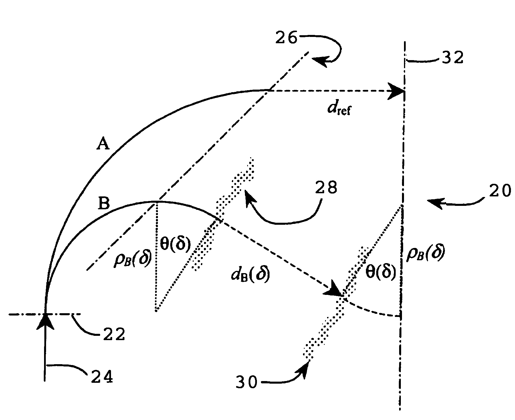
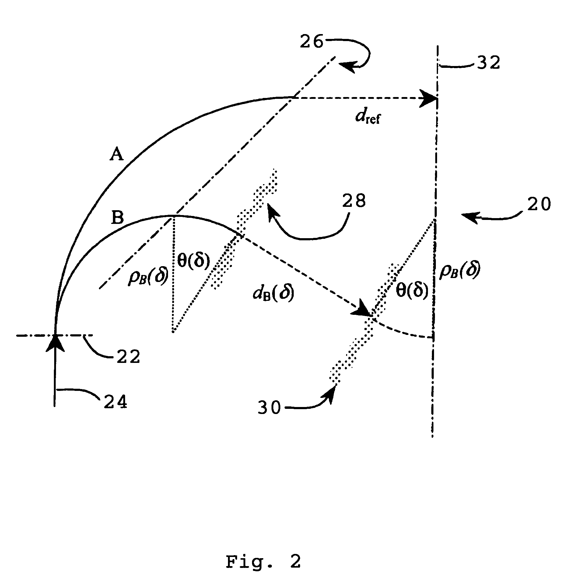
[0033]With reference to FIGS. 3–5, pole face contours and orbit geometries are shown for three example CMMBAs. These example CMMBAs were evaluated in each case by solving the above equations for θ(δ) and dB(δ) at ten momenta ranging from δ=1, where by definition θ(δ=1)=0 and dB(δ=1)=dref, to δ=0.1 in steps of Δδ=0.1. A compaction function F(δ)=M56(1−δ) was used to illustrate how a specific compaction spectrum may be imposed on the CMMBA. In this particular case, where the selected compaction spectrum is M56 and all nonlinear compactions are zero, an FEL driver ERL with 750 MHz RF accelerating −20° off-crest and using third harmonic RF linearization for bunch length and energy compression.

[0034]Referring to FIG. 6, a conceptual schematic is shown of the FIG. 3 and FIG. 5 arcs in compact FEL driver of the type discussed in the technical paper by D. Douglas entitled “A Compact Mirror-Bend-Achromat-Based Energy Recovery Transport System for an FEL Driver”, Jefferson Lab Technical Paper ...


PUM


Abstract

A method for controlling the momentum compaction in a beam of charged particles. The method includes a compaction-managed mirror bend achromat (CMMBA) that provides a beamline design that retains the large momentum acceptance of a conventional mirror bend achromat. The CMMBA also provides the ability to tailor the system momentum compaction spectrum as desired for specific applications. The CMMBA enables magnetostatic management of the longitudinal phase space in Energy Recovery Linacs (ERLs) thereby alleviating the need for harmonic linearization of the RF waveform.

Description

[0001]The United States of America may have certain rights to this invention under Management and Operating contract No. DE-AC05-84ER 40150 from the Department of Energy.FIELD OF THE INVENTION[0002]The present invention relates to charged particle accelerators and particularly to a method for controlling the momentum compaction in a beam of charged particles.BACKGROUND OF THE INVENTION[0003]The use of mirror-bend achromats (MBAs) has been proposed in energy recover linear accelerators (ERLs) for manipulating the path of charged particles. The MBA is typically a linear, large acceptance beam deflection system. The effectiveness of the MBA is, however, limited by the restricted range of momentum compactions available in the conventional mirror-bend design.[0004]In a conventional mirror-bend design, the compactions are completely constrained by the gross MBA geometry, including the bend radius and angle, and are inherently positive and linear. As a result, the conventional MBA necessit...

Claims


Application Information

Patent Timeline
IPC IPC(8): H01J3/00H01J3/12H05H7/00
CPCH05H7/00
Inventor DOUGLAS, DAVID
Owner JEFFERSON SCI ASSOCS LLC
Why Eureka
Try Eureka