
Remote monitoring apparatus using a mobile videophone

a mobile videophone and remote monitoring technology, applied in the field of remote monitoring systems, can solve the problems of difficult installation and maintenance high installation and maintenance costs of conventional remote monitoring systems, etc., and achieve the effect of inexpensive remote monitoring and searching

Inactive Publication Date: 2005-10-18
SAMSUNG ELECTRONICS CO LTD
View PDF18 Cites 54 Cited by
  • Summary
  • Abstract
  • Description
  • Claims
  • Application Information

AI Technical Summary

Benefits of technology

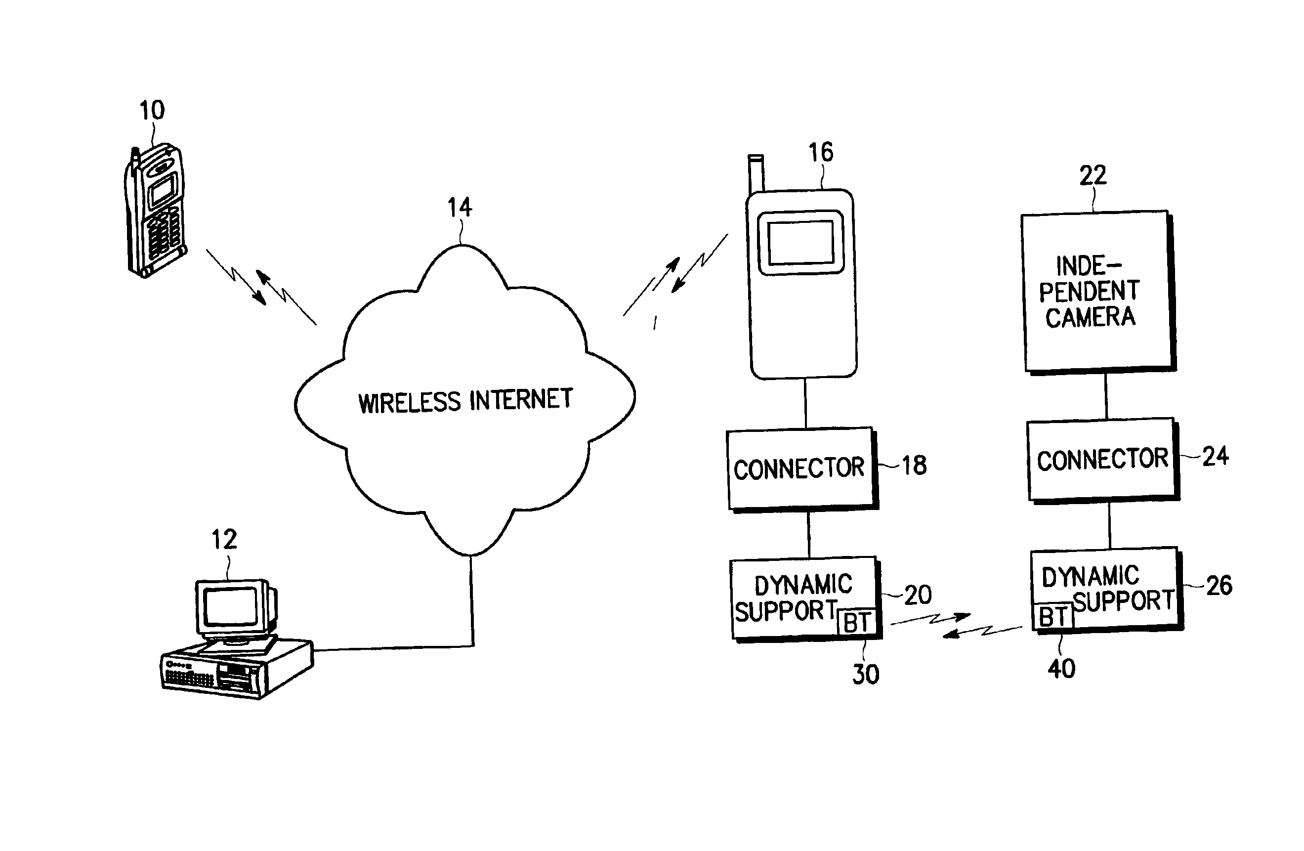
The present invention provides an apparatus for remote monitoring using a mobile videophone. The apparatus includes a control / monitoring unit, a mobile communication terminal with a camera, and a dynamic support located in a remote place to be monitored. The dynamic support controls the posture of the mounted mobile communication terminal and positional movement of the dynamic support upon receiving a posture / position control command on the mounted mobile communication terminal from the control / monitoring unit via the wireless Internet and the mounted mobile communication terminal. The technical effects of the invention are that it provides an inexpensive and efficient way to perform remote monitoring and searching using simple equipment, and it allows for dynamic control of the mobile communication terminal's posture and positional movement.

Problems solved by technology

However, the conventional remote monitoring system costs a great deal for installing the camera on the pan-and-tilt pedestal and needs a lot of additional equipments for controlling the remotely situated camera.
This makes it difficult to install and maintain the conventional remote monitoring system.
Moreover, when the number of remote places to be monitored through the conventional remote monitoring system increases, the scale of the conventional remote monitoring system is unacceptably enlarged.

Method used


Image

  • Remote monitoring apparatus using a mobile videophone
  • Remote monitoring apparatus using a mobile videophone
  • Remote monitoring apparatus using a mobile videophone

Examples


Embodiment Construction

[0016]A preferred embodiment of the present invention will be described herein below with reference to the accompanying drawings. In the following description, well-known functions or constructions are not described in detail since they would obscure the invention in unnecessary detail.

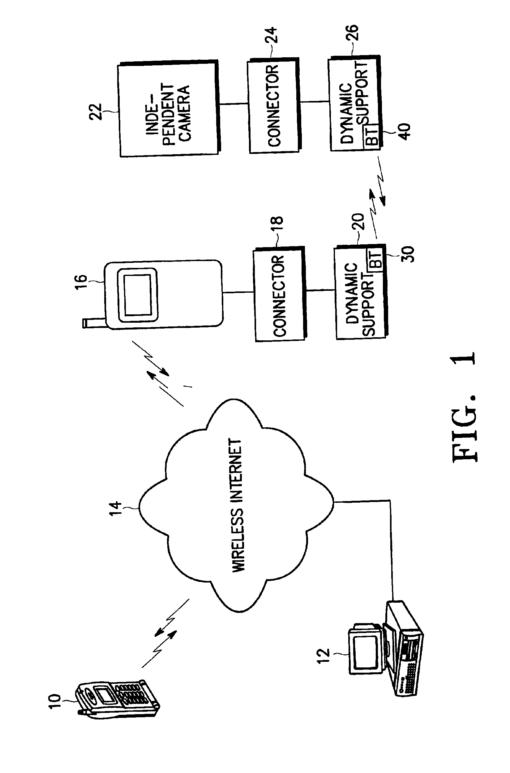
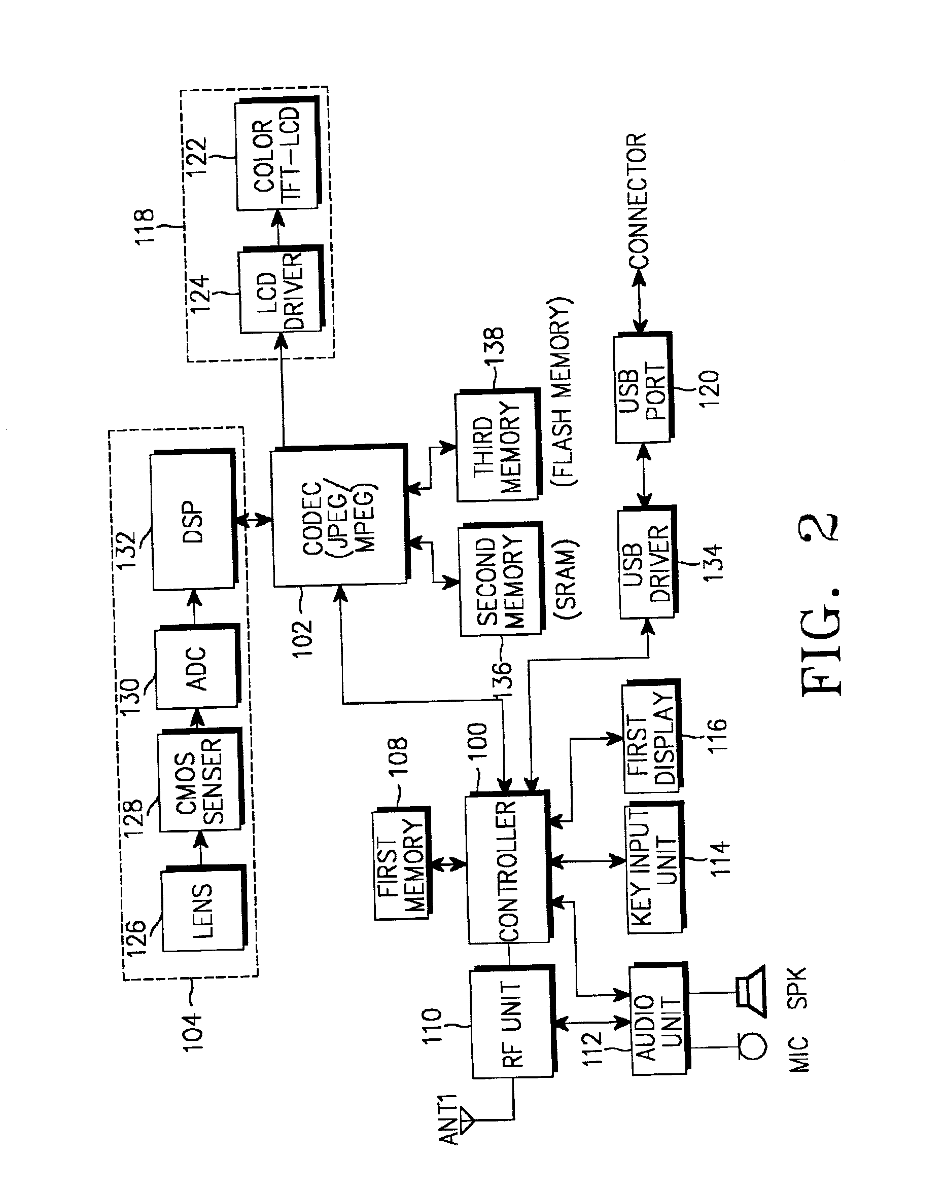
[0017]FIG. 1 is a schematic diagram of a remote monitoring system according to an embodiment of the present invention. Referring to FIG. 1, mobile videophones 10 and 16 each have a camera unit and can compress and transmit a moving picture through long-distance wireless communication. The mobile videophone 16 mounted on a dynamic support 20 is a mobile communication terminal carried by a user, and is used for photographing and transmitting a spot picture of a remote place. An independent camera 22 mounted on a dynamic support 26 is additionally used for photographing and transmitting a spot picture of a remote place. The mobile videophone 16 and the independent camera 22 perform a local (short-distanc...


PUM


Abstract

Disclosed is a remote monitoring apparatus comprising a control / monitoring unit located in a user's place for remote monitoring; a mobile communication terminal with a camera for photographing a subject, for performing a call service and an image processing / transmission service including an operation of photographing a subject with the camera; and a dynamic support located in a remote place to be monitored and having the mobile communication terminal mounted on the dynamic support itself, for controlling a posture of the mounted mobile communication terminal and positional movement of the dynamic support itself upon receiving a posture / position control command on the mounted mobile communication terminal from the control / monitoring unit via the wireless Internet and the mounted mobile communication terminal.

Description

PRIORITY[0001]This application claims priority to an application entitled “Remote Monitoring Apparatus using a Mobile Videophone” filed in the Korean Industrial Property Office on Feb. 16, 2001 and assigned Ser. No. 2001-7670, the contents of which are hereby incorporated by reference.BACKGROUND OF THE INVENTION[0002]1. Field of the Invention[0003]The present invention relates generally to a remote monitoring system, and in particular, to an apparatus for performing remote monitoring using a mobile videophone.[0004]2. Description of the Related Art[0005]In the conventional remote monitoring system, a camera is mounted on a remotely situated pan-and-tilt pedestal, which is controlled by wire or controlled wirelessly with a remote controller within a limited radius. A remote place's picture photographed by the camera mounted on the pan-and-tilt pedestal is transmitted by wire to a monitoring terminal such as a computer.[0006]However, the conventional remote monitoring system costs a g...

Claims


Application Information

Patent Timeline
Patent Type & Authority Patents(United States)
IPC IPC(8): H04N7/14H04N7/18
CPCH04N7/185H04N7/148H04N2007/145H04N7/18
Inventor LIM, CHAE-WHANKIM, SOON-JIN
Owner SAMSUNG ELECTRONICS CO LTD
Learn More