Apparatus and method for packet-based media communications

a packet-based media and media communication technology, applied in the field of packet-based media communications, can solve the problems of large amount of signal processing power, noise that is combined during the mixing step, and inherently created latency within, so as to reduce the amount of processing power, reduce the latency of voice data packets, and reduce transcoding

Inactive Publication Date: 2005-10-18
RPX CLEARINGHOUSE
View PDF19 Cites 83 Cited by
  • Summary
  • Abstract
  • Description
  • Claims
  • Application Information

AI Technical Summary

Benefits of technology

[0015]There are numerous advantages of the embodiments of the present invention compared to well-known voice conferencing techniques. For one, all of the embodiments of the present invention reduce the amount of processing power required within the conference bridges. This is done by removing the need for an energy detection block and / or an outputting apparatus within the conference bridge. This, in turn, can reduce the latency for the voice data packets. Another advantage of some embodiments of the present invention is a reduced transcoding that must be done. This reduction could be caused by the reduced need to decompress the compressed voice signals within the conference bridge due to the independently received speech detection signals. Further, by transmitting voice data packets in some embodiments directly between the source of the voice data packets to the destination of the voice data packets, a significant reduction in transcoding can be achieved. Yet another advantage of embodiments of the present invention is the reduced concentration of traffic that results from the implementation of the combined embodiments. In this case, the conference bridge does not receive or transmit high bandwidth voice data packets, but rather receives and transmits control signals to manage the voice conference. This also reduces any strain that might occur on the limited input / output capacity for the conference bridge.

Problems solved by technology

A problem with this algorithm is the amount of noise that is combined during the mixing step, this noise comprising a background noise source corresponding to each of the telephone terminals 16 within the conference session.
These problems include the latency inherently created within the conference bridge 28, the considerable amount of signal processing power required, the cost of the conference bridge, the limited input / output capacity of the conference bridge, and the maintenance and management of the conference bridge that is required.
These problems include possible variable delays, out-of-sequence packets, lost packets, and / or unbounded latency.
One problem with the setup depicted within FIG. 2 is the degradation of the voice signals as the voice signals are converted from PCM format to compressed format and vice versa within the conference bridge 28, these conversions together being referred to generally as transcoding.
A further problem results from the considerable latency that the processing within the conference bridge 28.
The latency of this processing can result in a significant delay between when the talker(s) speaks and when the other participants in the conference session hear the speech.
This delay can be noticeable to the participants if it is beyond the perceived real-time limits of human hearing.
This could result in participants talking while not realizing that another participant is speaking.
Yet another key problem with the design depicted in FIG. 2 is the considerable amount of signal processing power that is required to implement the conference bridge 28.
This considerable amount of required signal processing power is expensive.
Even further, another key problem within current conference bridge designs is their limited input / output capacity.
As well, a large number of participants within a conference session could put a strain on the capacity of the packet-based network 20 itself due to the concentration of traffic that occurs with the use of packet-based conference bridges.

Method used


Image

  • Apparatus and method for packet-based media communications
  • Apparatus and method for packet-based media communications
  • Apparatus and method for packet-based media communications

Examples


first embodiment

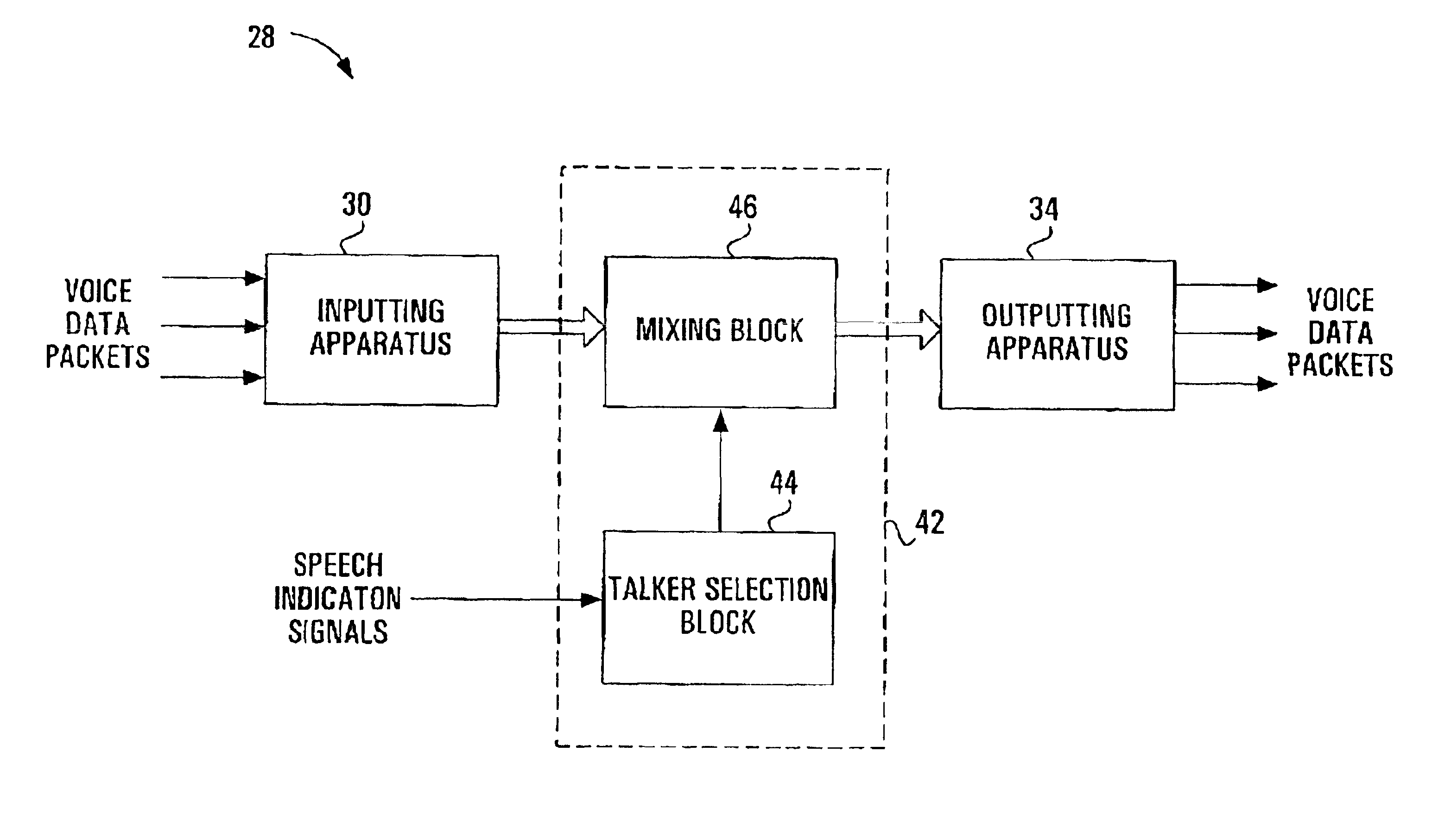
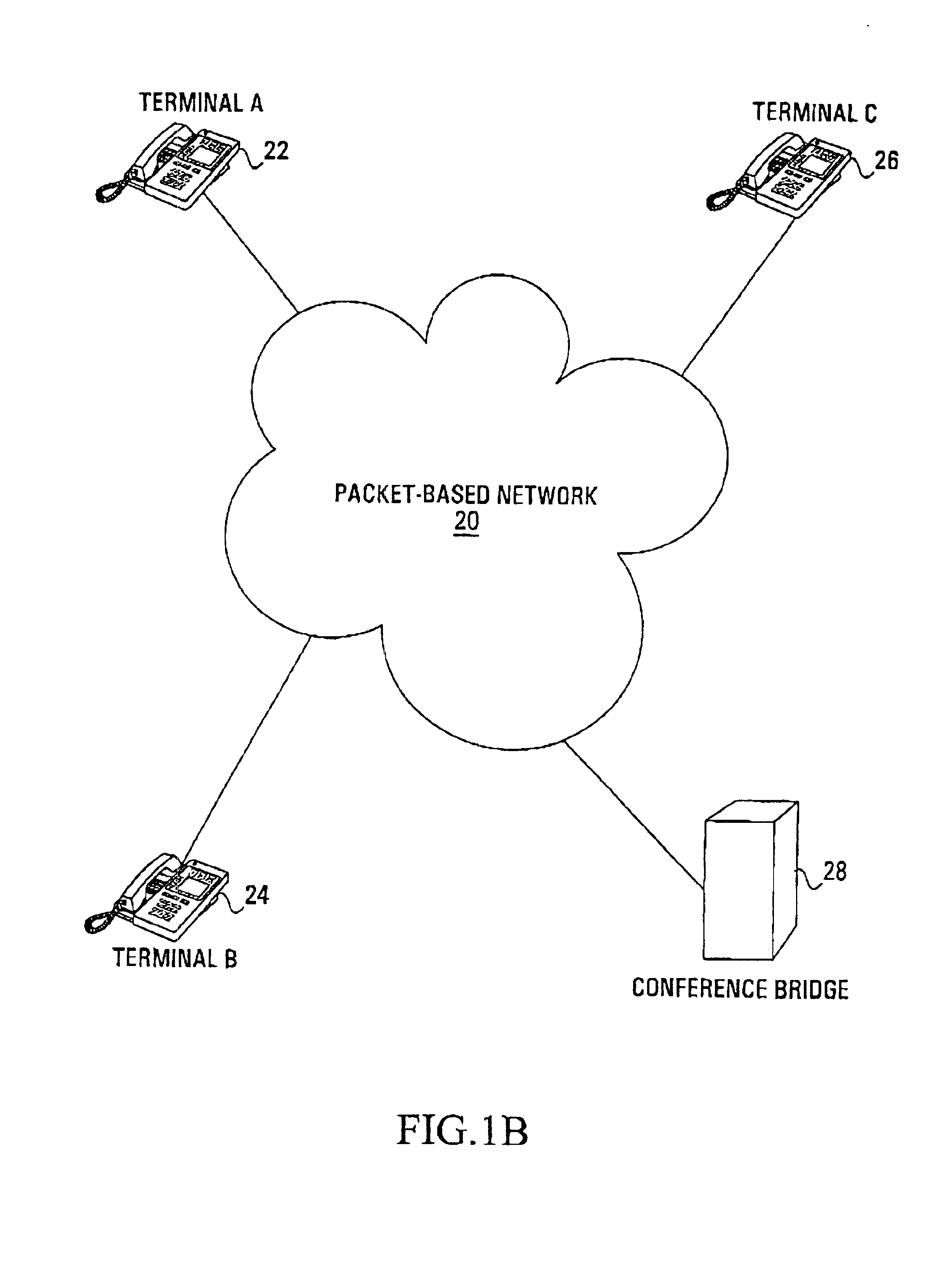
[0043]the present invention, in which reduced processing is required within the packet-based conference bridge compared to well-known conference bridge designs, is now described with reference to FIGS. 4, 5, 6A and 6B. In this embodiment, speech indication signals are sent from the packet-based terminals 22,24,26 within the voice conference to the packet-based conference bridge 28 so that no speech detection operation needs to be performed within the conference bridge itself. in one implementation, these speech indication signals simply indicate if a participant corresponding to a particular packet-based terminal is speaking or not. In other implementations, the speech indication signals indicates other parameters that could be utilized by a talker selection algorithm to select a set of the packet-based terminals as talkers. For example, in one implementation, the parameters within the speech indication signals correspond to the energy level of the speech associated with the partici...

second embodiment

[0070]FIG. 7 is a logical block diagram illustrating a packet-based conference bridge according to the present invention. This packet-based conference bridge replaces within FIG. 1B, the well-known packet-based conference bridge depicted within FIG. 2. As depicted in FIG. 7, the packet-based conference bridge 28 comprises the inputting apparatus 30 similar to that described above with reference to FIG. 2. The difference in the packet-based conference bridge 28 of FIG. 7 is the removal of the energy detection, talker selection and mixing block 32 and the outputting apparatus 34 and the insertion of energy detection and talker selection block 100 coupled to the inputting apparatus 30.

[0071]In operation, the energy detection and talker selection block 100 receives the voice signals corresponding to participants within a voice conference from the inputting apparatus 30, performs an energy detection operation on the received voice signals to determine which packet-based terminals within ...

third embodiment

[0089]In this third embodiment of the present invention, the packet-based conference bridge 28 is reduced to simply a talker selection block 150 as illustrated in FIG. 11. The talker selection block 150 operates in similar fashion to talker selection block 44 in terms of selecting talkers based upon the received speech indication signals while the block 150 operates in similar fashion to block 100 in terms of sending addressing control signals based upon the selection of the talker(s). The talker selection block 150 could be implemented in numerous manners similar to the blocks 44,100 described above with reference to FIGS. 4 and 7 respectively.

[0090]FIG. 12 is a logical block diagram illustrating a packet-based terminal according to the third embodiment of the present invention. As depicted within FIG. 12, the packet-based terminal comprises similar components to the packet-based terminal described above with reference to FIG. 8 but additionally comprising the speech detector 66 pr...


PUM


Abstract

The performance of a voice conference using a packet-based conference bridge can be improved with a number of modifications. In one modification, the conference bridge receives speech indication signals from the individual packet-based terminals within the voice conference, these speech indication signals then being used by the conference bridge to select the talkers within the voice conference. This removes the need for speech detection techniques within the conference bridge, hence decreasing the required processing power and the latency within the conference bridge. In another modification, the conference bridge sends addressing control signals to the individual packet-based terminals selected as talkers, these addressing control signals directing the terminals selected as talkers to directly transmit their voice data packets to the other terminals within the voice conference. This direct transmission of voice data packets can reduce transcoding and latency within the network. These two modifications could further be combined, resulting in a conference bridge that receives speech indication signals, selects the talkers for the voice conference and outputs addressing control signal to the talkers. In this case, the advantages of the two modifications are gained as well as additional capacity advantages resulting from no voice signals actually traversing the conference bridge.

Description

FIELD OF THE INVENTION[0001]This invention relates generally to packet-based media communications and more specifically to media conferencing within a packet-based communication network.BACKGROUND OF THE INVENTION[0002]Prior to the use of packet-based voice communications, telephone conferences were a service option available within standard non-packet-based telephone networks such as Pulse Code Modulation (PCM) telephone networks. As depicted in FIG. 1A, a standard telephone switch 15 is coupled to a plurality of telephone terminals 16 to be included within a conference session as well as a conference bridge 17. It is noted that these telephone terminals 16 are coupled to the telephone switch 15 via numerous other telephone switches (not shown) The telephone switch 15 forwards any voice communications received from the terminals 16 to the conference bridge 17, which then utilizes a standard algorithm to control the conference session.[0003]One such algorithm used to control a confe...

Claims


Application Information

Patent Timeline
Patent Type & Authority Patents(United States)
IPC IPC(8): H04M7/00H04M3/56
CPCH04M3/561H04M3/569H04M2207/203
Inventor SIMARD, FREDERIC F.CUDDY, DAVID R.EDHOLM, PHILIP K.
Owner RPX CLEARINGHOUSE
Why Eureka
Try Eureka