Valve with pressurization rate reduction device

a valve and pressure reduction technology, applied in the direction of valve operating means/releasing devices, valve types, pressure relieving devices on sealing faces, etc., can solve the problems of escaping the filter, and catching particles in the valve when the initial flowpath is opened, so as to reduce the chance of igniting, prevent intense adiabatic compression of gas, and reduce the effect of adiabatic compression

Active Publication Date: 2005-10-25
SHERWOOD VALVE
View PDF33 Cites 19 Cited by
  • Summary
  • Abstract
  • Description
  • Claims
  • Application Information

AI Technical Summary

Benefits of technology

[0012]Accordingly, the present invention is structured to reduce the chance of igniting a fire in a device downstream of the valve, such as a regulator on an oxygen cylinder, by addressing two of the possible sources of combustion, heat of compression ignition and particle impact ignition. First, the initial flowpath, by virtue of the size of the micro-passage, prevents an intense adiabatic compression of the gas upon opening of the initial flowpath. The fluid, and attendant pressure, that passes through the initial flowpath significantly reduce, or eliminate, the adiabatic compression of the gas created when the primary flowpath is opened. Thus, the chance of heat of compression ignition occurring is reduced or eliminated. Second, any particulate matter picked up by the fluid flow when the initial flowpath is opened and which travels into the valve is trapped by the filter. Additionally, the tubular member moves the valve inlet away from the funnel shaped end of the cylinder, thereby reducing the chance of particulate matter flowing directly into the valve. Thus, the chance of particle impact ignition is reduced or eliminated.
[0013]It is an object of this invention to provide a valve that incorporates a device structured to reduce and control the rate of pressurization through the valve.
[0014]It is a further object of this invention to provide a valve that incorporates a pressure rate reduction device that can be precisely controlled.

Problems solved by technology

Second, any particulate matter picked up by the fluid flow when the initial flowpath is opened and which travels into the valve is trapped by the filter.

Method used


Image

  • Valve with pressurization rate reduction device
  • Valve with pressurization rate reduction device
  • Valve with pressurization rate reduction device

Examples


Embodiment Construction

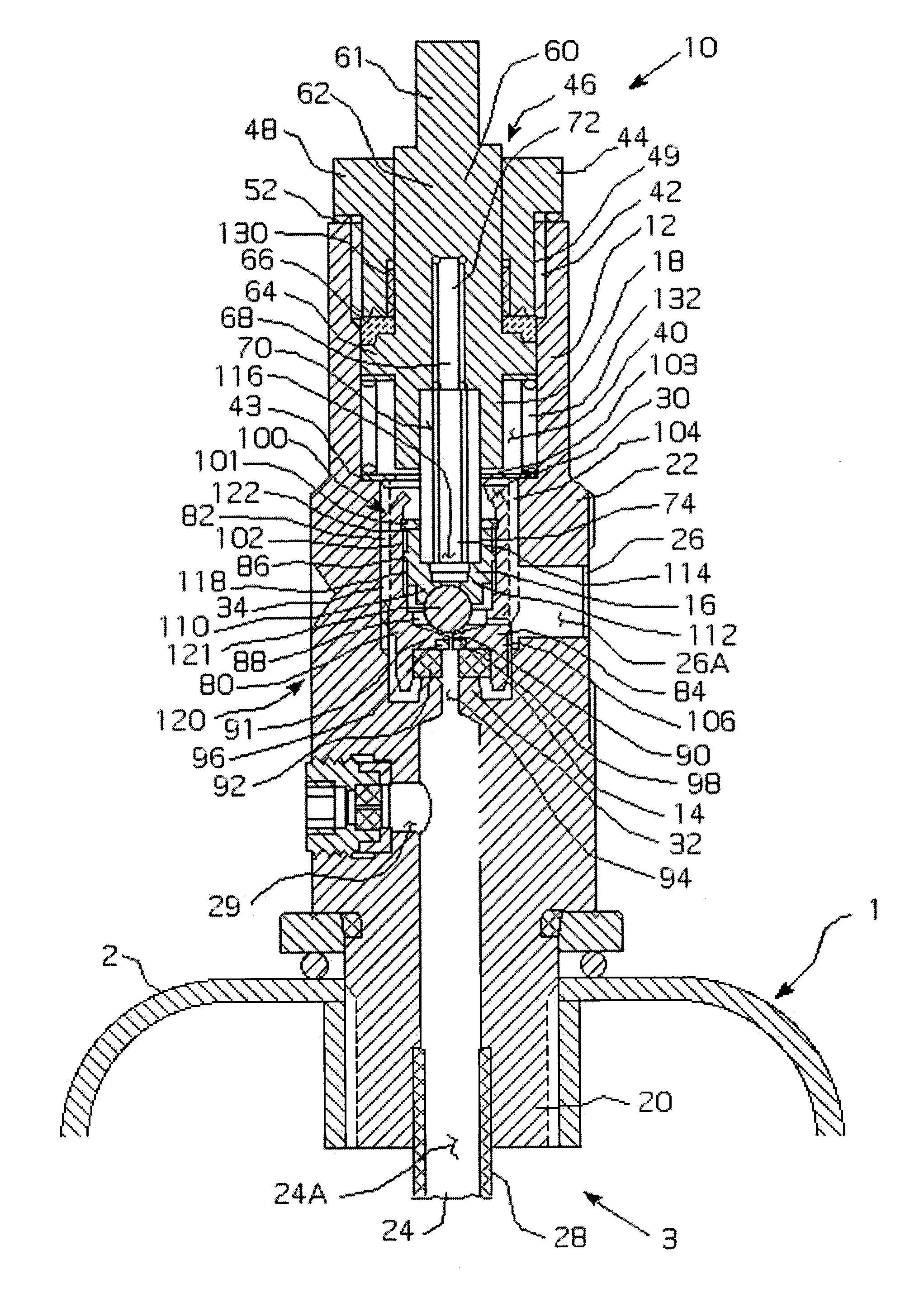
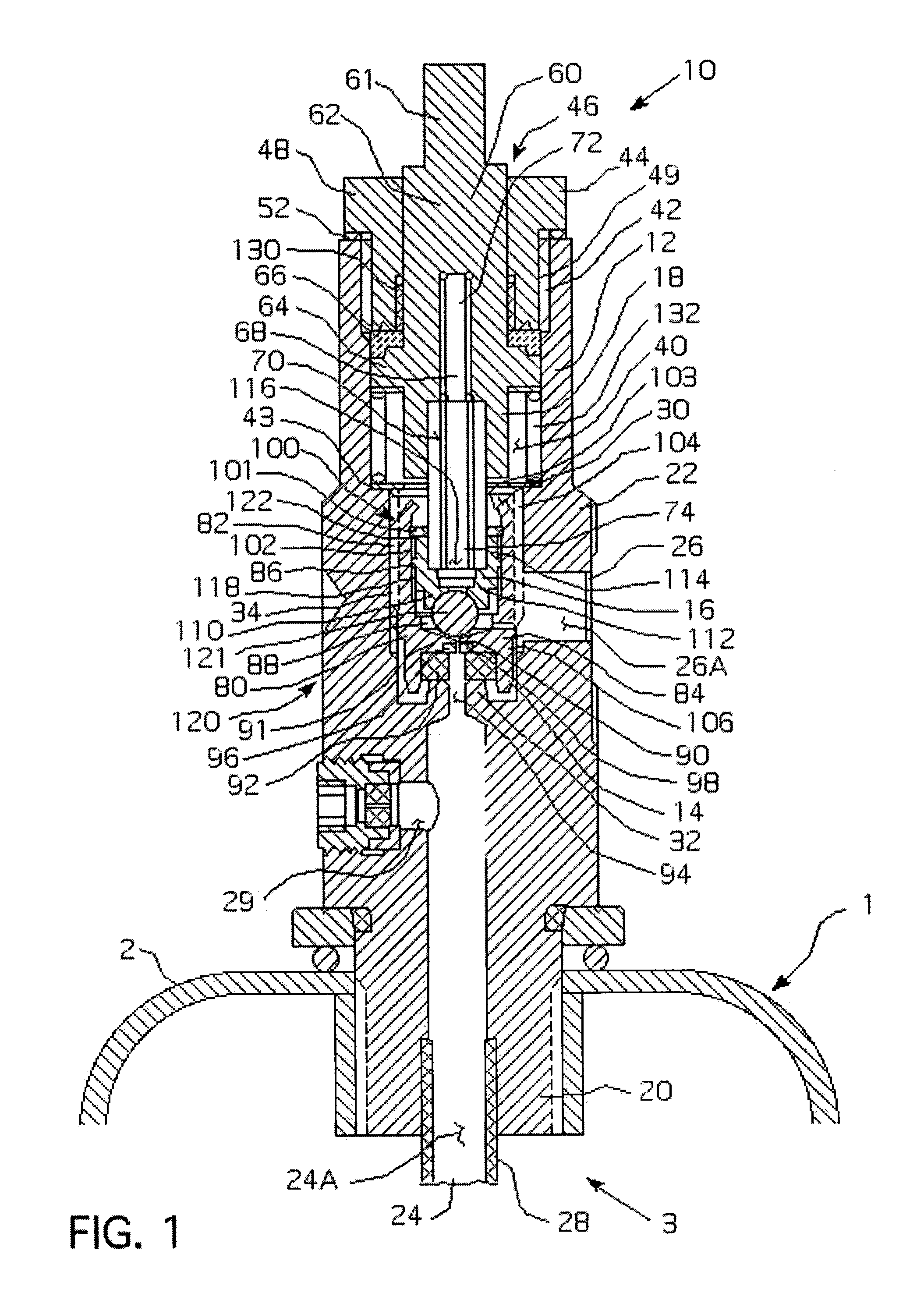
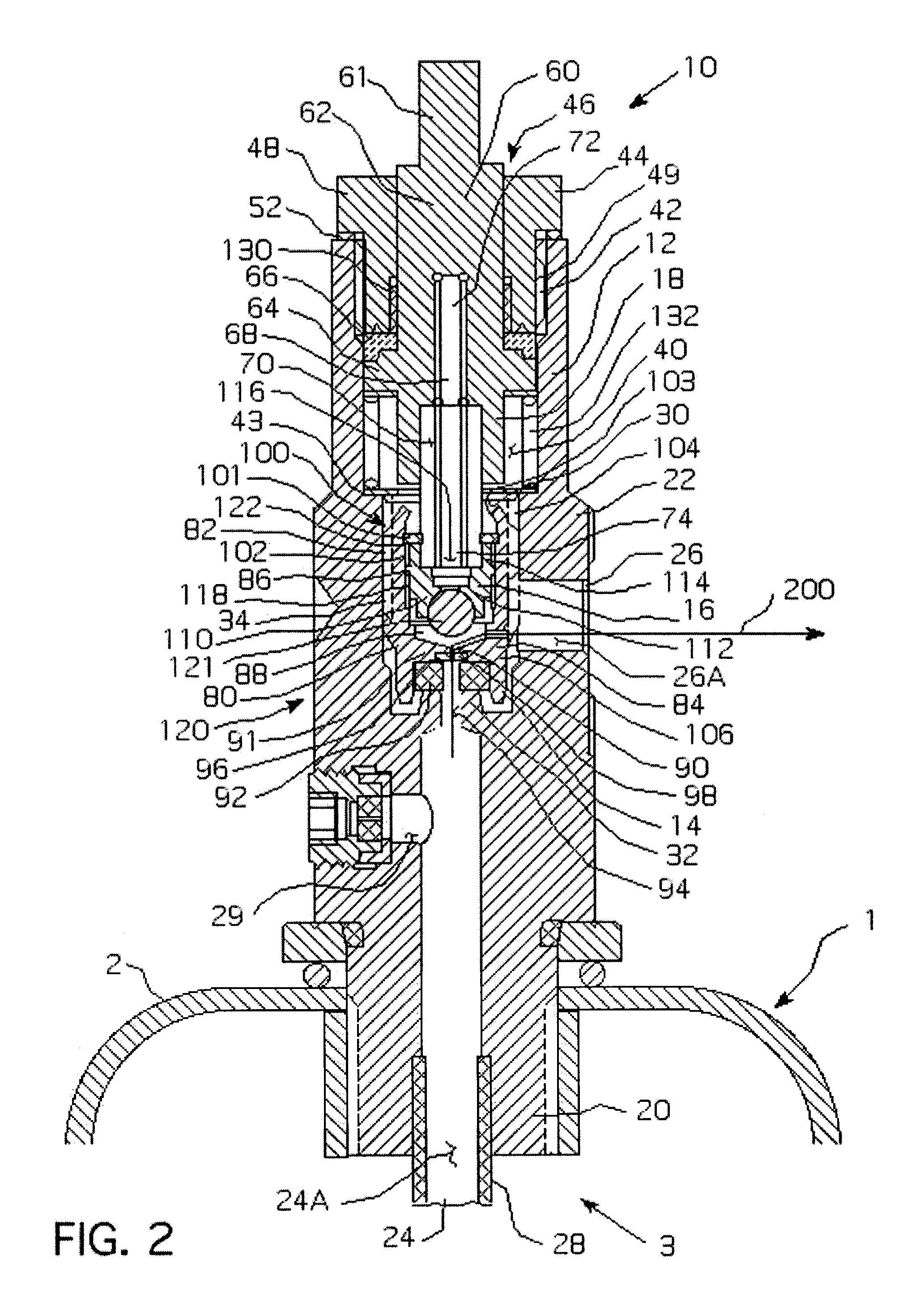
[0022]As used herein, any descriptive directional words, such as “upper” and “lower,” are used in reference to the Figures only whereas the valve may be oriented in any direction.

[0023]As shown in FIGS. 1–3, the valve 10 includes an elongated housing assembly 12, a first valve assembly 14, a second valve assembly 16, and a stem assembly 18. The housing assembly 12 includes a threaded attachment end 20, a generally square portion 22, and a generally cylindrical portion 23. The attachment end 20 is structured to engage a compressed gas cylinder 1. The cylinder 1 includes a rigid housing 2 having at least one opening 3 therethrough. The valve 10 is coupled to the cylinder 1 at the opening 3. The generally square portion 22 includes an outlet 26 which is at the end of an outlet passage 26a. The outlet passage 26a extends in a direction perpendicular to the axis of the housing assembly 12. The attachment end 20 includes an inlet that is at the end of an inlet passage 24a. The inlet passa...


PUM


Abstract

A valve includes a housing assembly, a stem assembly and a surge suppression device. The surge suppression device includes an initial flowpath between the valve inlet and the outlet, a primary flowpath between the inlet and the outlet, a first valve assembly and a second valve assembly. The first valve assembly is coupled to the stem assembly and threadably engages the housing assembly and structured to move between a first, closed position wherein the primary flowpath is blocked and a second, open position wherein the primary flowpath is not blocked. The second valve assembly is threadably coupled to the housing assembly and structured to move between a first, closed position wherein the initial flowpath is blocked and a second, open position wherein the initial flowpath is not blocked.

Description

BACKGROUND OF THE INVENTION[0001]1. Field of the Invention[0002]This application relates to a valve for a high pressure system and, more specifically, to a valve for use with a high pressure cylinder that incorporates a devices structured to reduce the rate of pressurization of a downstream device.[0003]2. Background Information[0004]Valves coupled to a high pressure gas cylinders are well known in the art. Such valves typically open in a single stage. That is, when a user operates an opening mechanism, typically a handle or knob, a valve assembly blocking the flowpath between the valve inlet and outlet moves from a closed position to an open position. When the flowpath is initially opened there is adiabatic compression of the gas through the valve and any downstream devices. While this adiabatic compression of the gas does not effect the valve, it has been determined that certain devices coupled to the downstream side of the valve may be adversely effected. For example, a downstrea...

Claims


Application Information

Patent Timeline
Patent Type & Authority Patents(United States)
IPC IPC(8): F16K1/54F16K1/32F16K17/04
CPCF16K17/0406Y10T137/8122Y10T137/86976Y10T137/86984Y10T137/87008Y10T137/8704
Inventor BORTON, JEFFRE ALLENLECHNER, DAVID MICHAELSATTELBERG, DENNIS HERMAN
Owner SHERWOOD VALVE
Why Eureka
Try Eureka