Electrical connector with different pitch terminals

a technology of electrical connectors and terminals, applied in the direction of coupling contact members, coupling device connections, coupling/disassembly parts, etc., can solve the problems of increased risk of wire board wastage, increased risk of pcb wastage, and inconvenient and safe drilling of such holes, so as to save manufacturing costs for forming pcb. , the effect of convenient and safe drilling

Inactive Publication Date: 2005-10-25
HON HAI PRECISION IND CO LTD
View PDF6 Cites 29 Cited by
  • Summary
  • Abstract
  • Description
  • Claims
  • Application Information

AI Technical Summary

Benefits of technology

[0007]Accordingly, an object of the present invention is to provide an electrical connector with different pith terminals, thereby to increase a pitch of two adjacent holes defined in a PCB in which corresponding terminals of the electrical connector are secured, so that the holes can conveniently and safely be drilled in the PCB and manufacturing costs required to form the PCB can be saved.
[0008]To fulfill the above object, an electrical connector is applied according to the present invention. The electrical connector comprises a base, a first module received in the base, and a second module immovably attached to a bottom of the base. The first module comprises a housing and a plurality of first terminals secured in the housing in rows and columns. Each first terminal comprises a middle portion and upper and lower curved resilient arms extending from opposite ends of the middle portion. The upper and lower curved resilient arms are respectively formed with a finger and a leg. The second module comprises a substrate and a plurality of second terminals secured on the substrate. Each second terminal comprises a middle section, an upper mating portion extending from an end of the middle section and adapted to mechanically and electrically engage the leg of a corresponding first terminal, and a lower connecting portion extending from an opposite end of the middle section and adapted to be accommodate in a hole defined in a PCB. The middle section of at least one of the second terminals comprises a portion bent to offset the lower connecting portion of said at least one of the second terminals away from the upper mating portion of said at least one of the second terminals, so that fingers of two adjacent first terminals that mechanically and electrically engage two corresponding second terminals form a pitch less than that defined between two holes that electrically mate with said two corresponding second terminals. As a result, it is convenient and safe to drill or the like to define the holes in the PCB and manufacturing costs required to form the PCB is saved.

Problems solved by technology

Thus, it is increasingly difficult to drill such holes in the PCB and the risk of wastage of the drilled PCB is accordingly prone to increase.
This increases the risk of wastage of the wire boards 98 and manufacturing costs are accordingly sharply climbed up.

Method used


Image

  • Electrical connector with different pitch terminals
  • Electrical connector with different pitch terminals
  • Electrical connector with different pitch terminals

Examples


Embodiment Construction

[0025]Reference is now made to the drawings to describe the invention in detail.

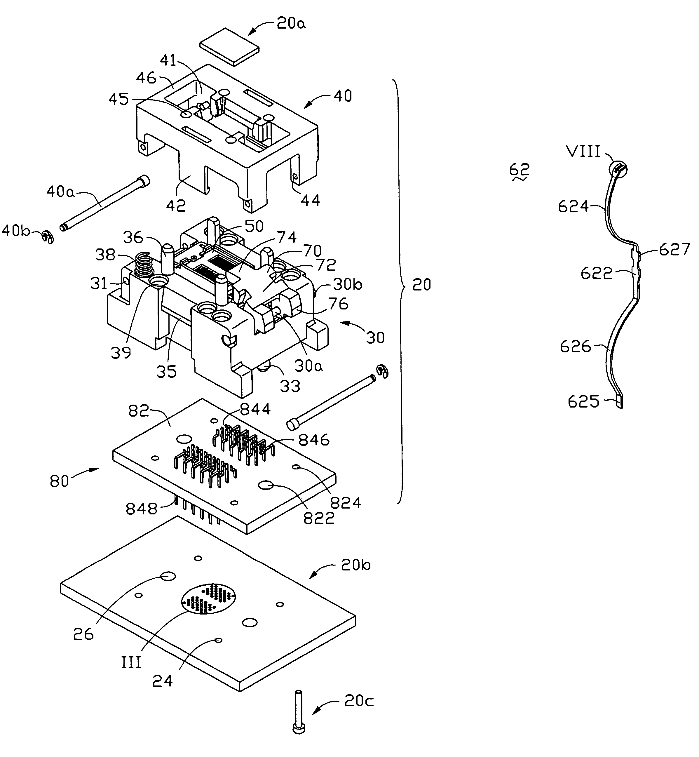
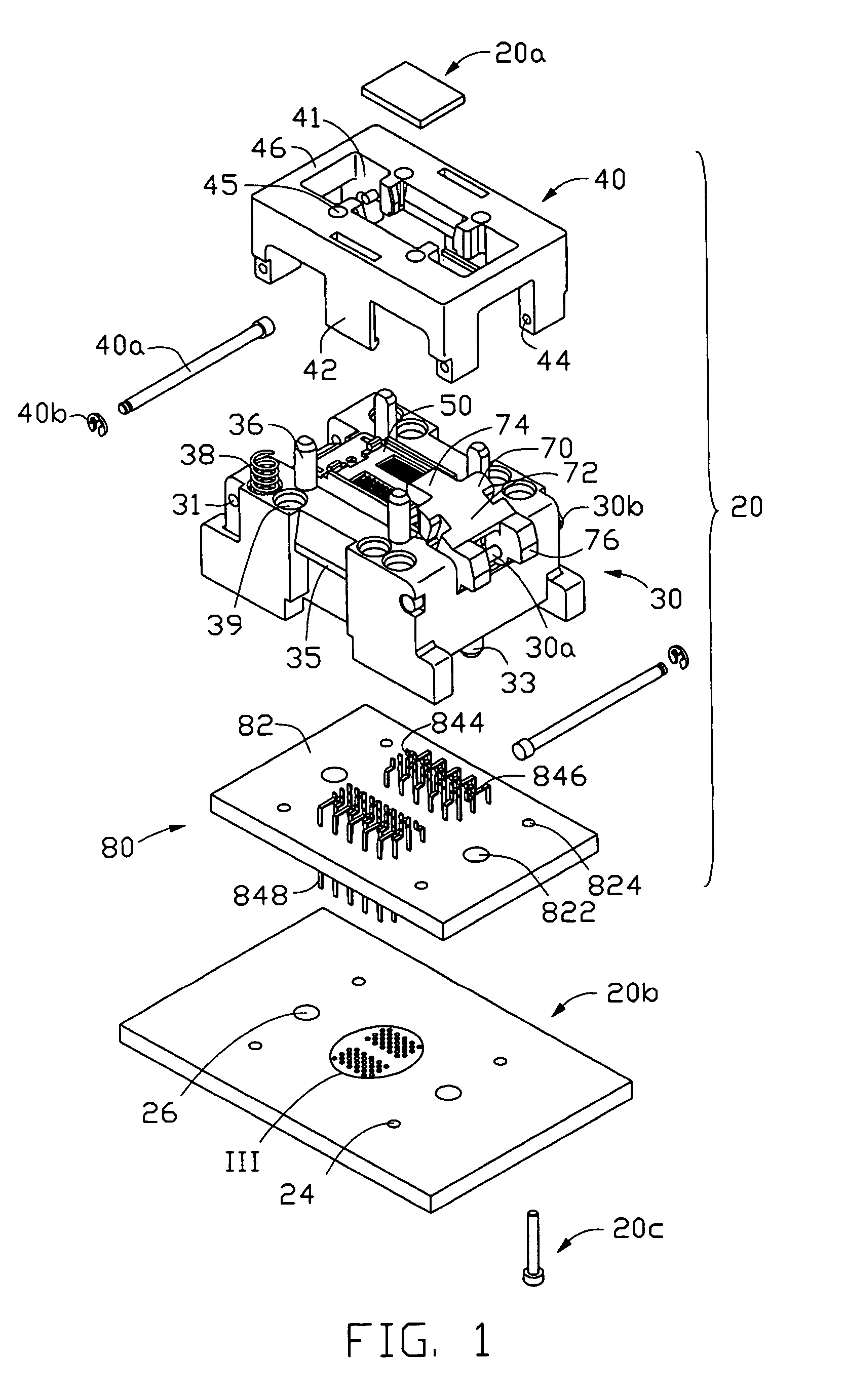
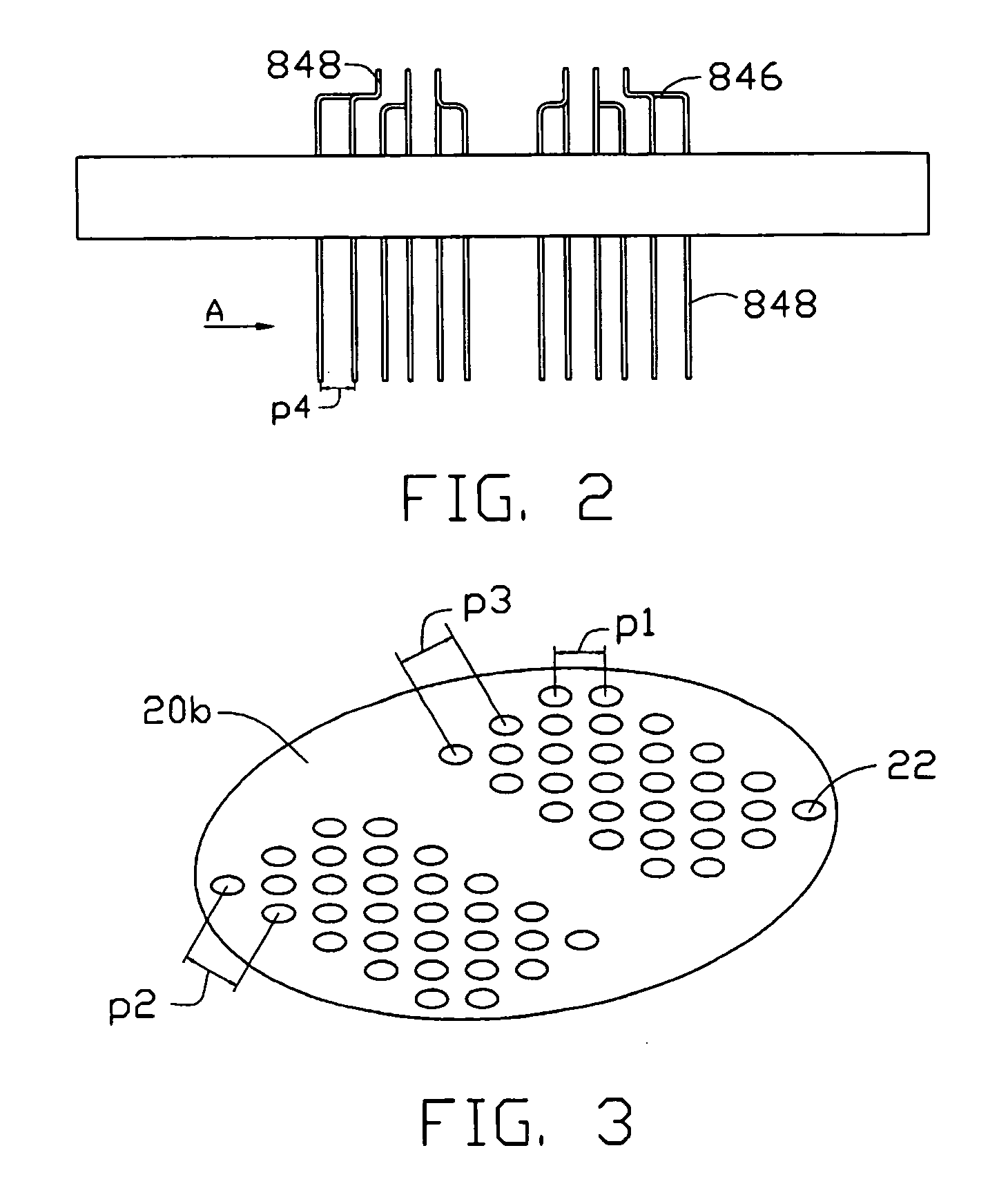
[0026]The electrical connector 20 applied according to the present invention is mainly used for electrically interconnecting an IC, such as a central processing unit (CPU) 20a, and an electrical substrate, such as a PCB 20b. It should be understood that the electrical connector 20 disclosed hereinafter may be used in other circumstances, such as in an event where an IC is tested by the electrical connector 20 mounted on a test board in high work temperature and voltage.

[0027]Referring to FIGS. 1 and 5, the electrical connector 20 includes a base 30, a lid 40 movably mounted on the base 30, a first module 60 received in the base 30, a cover 50 movably mounted on the first module 60, a second module 80 immovably attached to a bottom of the base 30 and a positioning mechanism 70 pivotally attached to the base 30.

[0028]Referring also to FIG. 11, the base 30 is formed from dielectric material and defines a ch...


PUM


Abstract

An electrical connector (20) mounted on a substrate (20b) defining holes (22) includes a base (30) and first and second terminals (62, 84) attached to the base. Each terminal has a retention portion (622) and a pair of curved arms (624, 626) extending from opposite ends of the retention portion. The pair of curved arms are respectively formed with upper and lower contact portions (623, 625). Each terminal has a securing portion (842) and upper and lower mating portions (844, 848) extending from opposite ends of the securing portion. Certain second terminals each have a bent portion (846) to make the pitch between the lower mating portions of two adjacent second terminals larger than that between the upper contact portions of two adjacent first terminals, thereby conveniently and safely drilling the holes of the substrate in which the lower mating portions are secured.

Description

BACKGROUND OF THE INVENTION[0001]1. Field of the Invention[0002]The present invention relates to the art of electrical connectors, and especially to a pin grid array (PGA) type socket connector for electrically interconnecting an integrated circuit (IC) with a printed circuit board (PCB).[0003]2. Description of the Prior Art[0004]Conventionally, a PGA-type socket connector comprises a plurality of conductive terminals inserted into corresponding holes of a PCB, thereby to achieve electrical engagement between the socket connector and the PCB. With the trend toward miniaturization of electrical components, the density of the terminals arrayed in the socket connector becomes more and more high to catch up with the trend. This results increasing the density of the holes to secure the terminals, namely, a pitch of two adjacent holes in the PCB in a row or column is relatively small or short. Thus, it is increasingly difficult to drill such holes in the PCB and the risk of wastage of the...

Claims


Application Information

Patent Timeline
Patent Type & Authority Patents(United States)
IPC IPC(8): H01R13/62H01R12/00H05K1/00H01R12/14H01R13/04H01R13/24H01R31/06
CPCH01R13/2435H01R13/2492H01R31/06H01R2201/20
Inventor PETERSEN, RICHARD W.HOU, SUNG-PEI
Owner HON HAI PRECISION IND CO LTD
Why Eureka
Try Eureka