Implantable venous valve

a venous valve and implantable technology, applied in the field of vascular implants, can solve the problems of reducing the flow of oxygenated blood to the brain, and possibly reducing the volume of blood available to the right heart, so as to enhance bio- and blood compatibility, restore native valve function, and duplicate the effect of function

Inactive Publication Date: 2005-10-25
BIOMEDICAL RES ASSOCS
View PDF10 Cites 121 Cited by
  • Summary
  • Abstract
  • Description
  • Claims
  • Application Information

AI Technical Summary

Benefits of technology

[0030]One advantage of the present invention resides in that the subject implantable device can be used to restore native valve function in patients who suffer chronic venous insufficiency, e.g., in the form of venous ulcers and/or varicose veins, or venous insufficiency following an episode of deep venous thrombosis (DVT), vascular injury, or venous dilation.
[0031]Another advantage of the present valve prosthesis is that it is constructed entirely from synthetic or nonbiological materials.
[0032]Another advantage of the present device is that it duplicates the function, although not the form, of th

Problems solved by technology

In the legs and arms, the transit time of this increased arterial pressure is delayed, resulting in a temporary drop in venous pressure.
Venous pressure drops as blood flow responds to body position change and gravity, thereby reducing the volume of blood available to the right heart and possibly reducing the flow of oxygenated blood to the brain.
In such a case, a person could become light headed, dizzy or experience syncope.
Health care costs in the United States are estimated at one billion dollars with a loss of 2 million days of productivity.
Skin changes and ulcers due to venous insufficiency usually result from valve damage or deep venous occlusion following a bout of DVT.
Active venous ulcers are the leading cause of leg ulcerati

Method used


Image

  • Implantable venous valve
  • Implantable venous valve
  • Implantable venous valve

Examples


Embodiment Construction

[0052]It is to be understood that both the foregoing general description and the following detailed description are exemplary and explanatory only and are not restrictive of the invention as claimed.

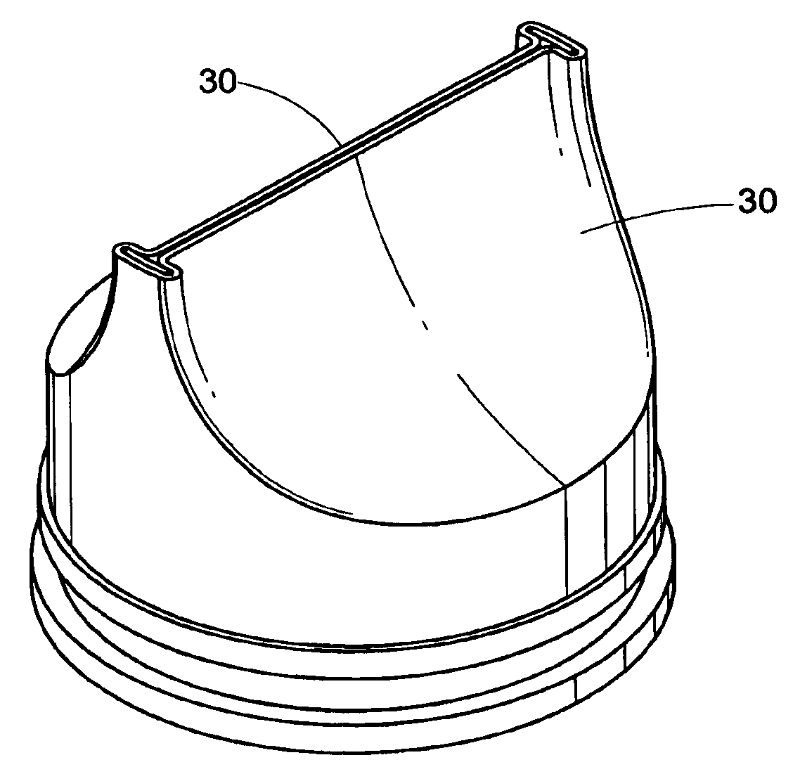
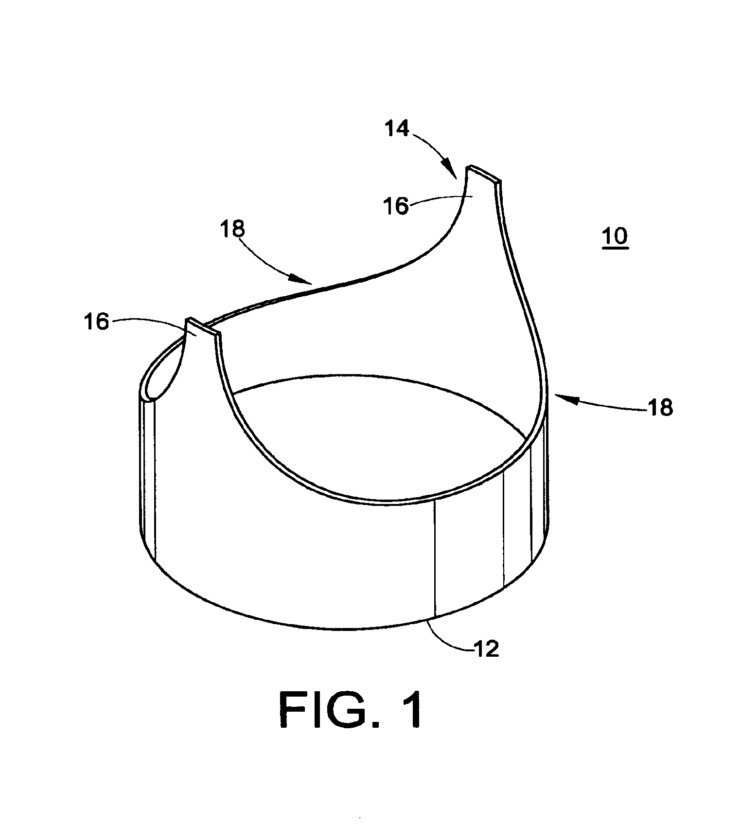
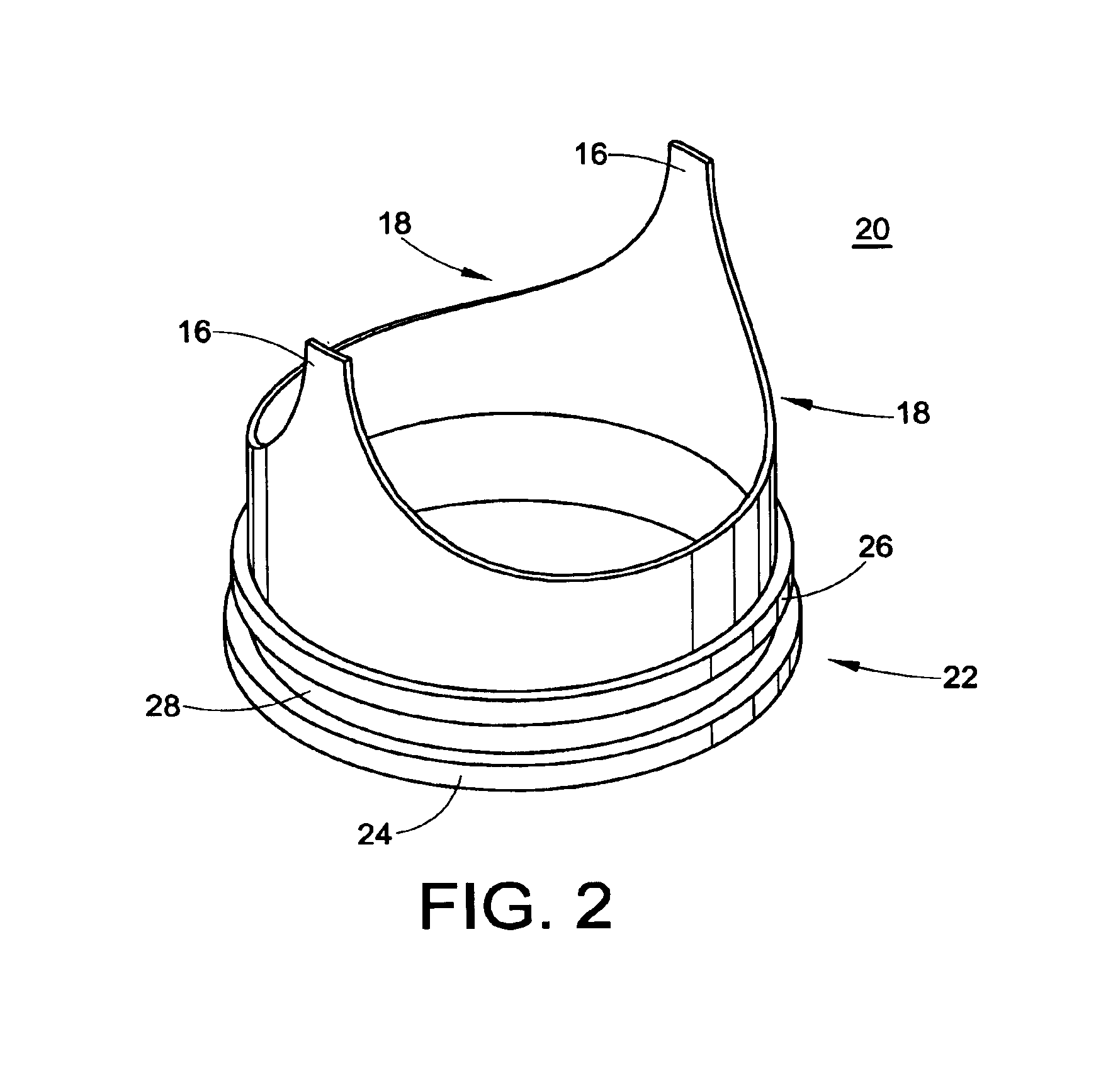
[0053]The present development is directed to a prosthetic vein valve for implantation within a blood vein or vascular graft, e.g., to replace a diseased or malfunctioning valve. The valve is made from synthetic material, preferably a polymeric material. The valvular prosthesis includes leaflets mounted on a support and positioned within a conduit, all of which cooperate to permit blood flow in one direction only. The leaflets will normally be in an open position, permitting blood to flow through the vein. The leaflets will close, blocking the flow of blood when blood begins to backflow in a direction opposite from its normal flow.

[0054]The implantable venous valve prosthetic device of the present invention is particularly suited to restore physiologic blood flow to the human leg in those...


PUM


Abstract

A venous valve prosthesis includes a hollow conduit (40) defining a central passageway through which blood may flow. Opposing, pliable leaflet members (30) are located within the conduit and move back and forth between a first, open position, whereby blood may flow through the central passageway in a first direction, and a second, closed position, whereby blood is prevented from backflowing through the central passageway in a second direction which is opposite the first direction. A hollow and generally cylindrical support member (10, 20) retains the leaflet members and is coaxially disposed within the conduit. The support member includes opposing cutaway regions (18) defining two axially extending struts (16) supporting the leaflet members. The cutaway regions, in cooperation with the struts, allow the leaflet members to collapse inwardly to the closed position.

Description

CROSS-REFERENCE TO RELATED APPLICATION[0001]The present application claims the priority benefit under 35 U.S.C. §119(e) of the U.S. Provisional Application Ser. No. 60 / 284,047, filed Apr. 16, 2001. Said Provisional Application is incorporated herein by reference in its entirety.BACKGROUND OF THE INVENTION[0002]The present invention relates generally to vascular implants and, more particularly, to a synthetic or artificial prosthetic valve device for implantation in a blood vein. In another aspect, the present invention relates to a method for making the same. In yet another aspect, the present invention relates to a method for implanting the venous valve device of the present invention. In still another aspect, the present invention relates to a method for the treatment, reversal, and / or prevention of venous insufficiency and its consequences in animals, including humans.[0003]Venous blood flow returns de-oxygenated blood from the distal extremities to the heart via two mechanisms. ...

Claims


Application Information

Patent Timeline
IPC IPC(8): A61F2/24A61F2/06
CPCA61F2/2412A61F2/2475A61F2/2418
Inventor ACOSTA, GEORGE M.KICK, GEORGE F.
Owner BIOMEDICAL RES ASSOCS
Why Eureka
Try Eureka