
Compensation sample and hold for voltage regulator amplifier

a voltage regulator and amplifier technology, applied in the field of compensation sample and hold for voltage regulator amplifiers, can solve problems such as misoperation of one or more devices

Active Publication Date: 2005-10-25
INTERSIL INC
View PDF2 Cites 93 Cited by
  • Summary
  • Abstract
  • Description
  • Claims
  • Application Information

AI Technical Summary

Benefits of technology

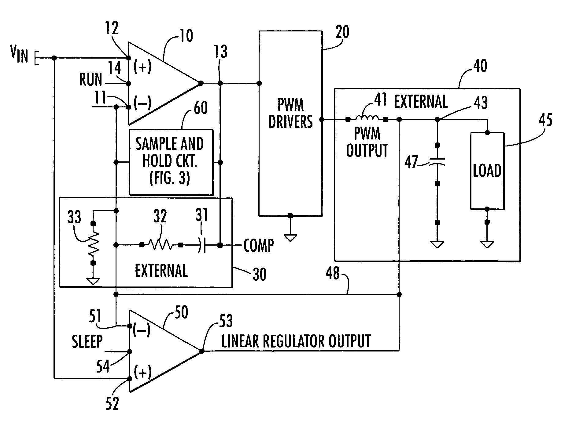
[0008]In accordance with the present invention, this problem is effectively obviated by controllably sampling and storing the voltage across the AC compensation filter, in response to a transition of the operation of a DC power supply from run or active mode to quiescent or sleep mode. This sampled voltage is retained as a compensation voltage throughout the quiescent mode, so that it will be immediately available to the PWM circuitry at the termination of the quiescent interval. This serves to ensure a relatively smooth (low noise) power supply switch-over during a subsequent transition from quiescent to active mode.
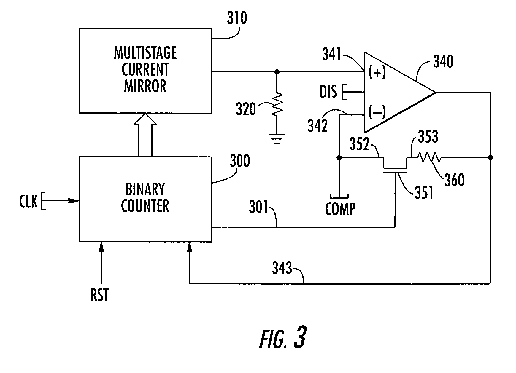
[0010]In response to a run-to-sleep mode transition of the power supply circuit, the compensation amplifier and the counter are enabled, with the counter being sequentially incremented by a clock signal. As the counter is clocked, associated current mirror stages of the multistage current mirror sequentially increment the magnitude of current being summed through the summing resistor. When the summed currents produce a voltage across this resistor that equals the value of the compensation voltage at the compensation pin COMP, the output of the compensation amplifier changes stage, freezing the count value in the counter. This also places the compensation amplifier in a unity gain mode, so that the voltage at the compensation pin COMP is held at its current value. Upon returning to RUN mode, this maintained compensation voltage is immediately available to the PWM circuitry, so that a smooth transition between sleep and run mode is provided.

Problems solved by technology

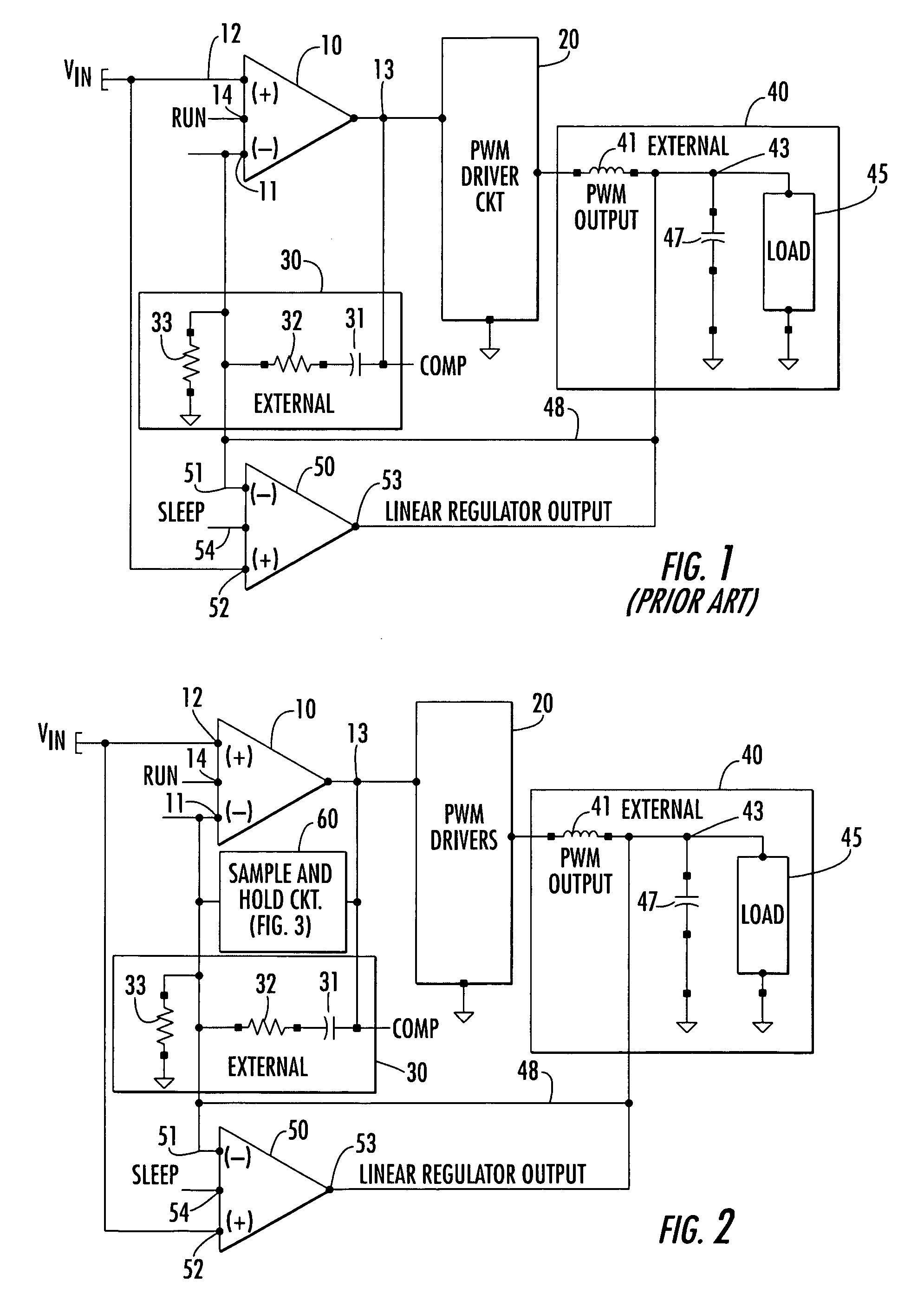
During this interval, the output node 43 provides a voltage that is different from the correct value and appears to downstream powered devices as a power rail anomaly, which can cause misoperation of one or more devices.

Method used


Image

  • Compensation sample and hold for voltage regulator amplifier
  • Compensation sample and hold for voltage regulator amplifier
  • Compensation sample and hold for voltage regulator amplifier

Examples


Embodiment Construction

[0014]Before describing a non-limiting, but preferred embodiment of the sample and hold-based, voltage compensation circuit of the present invention, it should be observed that the invention resides primarily in an arrangement of conventional circuit components, and the manner in which they may be incorporated into a PWM-controlled DC—DC converter of the type described above. It is to be understood that the present invention may be embodied in a variety of other implementations, and should not be construed as being limited to only the embodiment shown and described herein. Rather, the implementation example shown and described here is intended to supply only those specifics that are pertinent to the present invention, so as not to obscure the disclosure with details that are readily apparent to one skilled in the art having the benefit of present description. Throughout the text and drawings like numbers refer to like parts.

[0015]As pointed out briefly above, and as diagrammatically...


PUM


Abstract

The problem of charge leakage in the AC compensation filter for the error amplifier of a pulse width modulation (PWM)-based DC—DC converter is effectively obviated by controllably sampling and storing the voltage across the AC compensation filter, in response to a transition of the operation of a DC power supply from run or active mode to quiescent or sleep mode. The sampled voltage is retained as a compensation voltage throughout the quiescent mode, so that it will be immediately available to the PWM circuitry at the termination of the quiescent interval. This serves to ensure a relatively smooth (low noise) power supply switch-over during a subsequent transition from quiescent to active mode.

Description

CROSS-REFERENCE TO RELATED APPLICATION[0001]The present application claims the benefit of co-pending U.S. Application Ser. No. 60 / 435,679, filed Dec. 20, 2002, by P. Sferrazza et al, entitled: “Compensation Sample And Hold For Voltage Regulator Amplifier,” assigned to the assignee of the present application and the disclosure of which is incorporated herein.FIELD OF THE INVENTION[0002]The present invention relates in general to DC power supply circuits and components therefor, and is particularly directed to a circuit arrangement for sampling and holding the voltage across an AC compensation filter installed in a feedback path of a voltage regulator error amplifier for a pulse width modulator, in response to a transition of the operation of a DC power supply from active mode of operation to quiescent mode of operation. By retaining this voltage throughout quiescent mode, the circuit arrangement of the invention is operative to ensure a relatively smooth (low noise) power supply swit...

Claims


Application Information

Patent Timeline
Patent Type & Authority Patents(United States)
IPC IPC(8): G05F5/00H02M1/36
CPCH02M1/36
Inventor SFERRAZZA, PAUL K.WIETECHA, STANLEY F.
Owner INTERSIL INC
Learn More