Device for capturing thermal spectra from tissue

Inactive Publication Date: 2005-10-25
OPTISCAN BIOMEDICAL
View PDF46 Cites 219 Cited by
  • Summary
  • Abstract
  • Description
  • Claims
  • Application Information

AI Technical Summary

Benefits of technology

[0008]A device and method are provided for use with a noninvasive optical measurement system, such as a thermal gradient spectrometer, for improved determination of analyte concentrations within living tissue. In one embodiment, a wearable window is secured to a patient's forearm thereby isolating a measurement site on the patient's skin for determination of blood glucose levels. The wearable window effectively replaces a window of the thermal gradient spectrometer, and thus forms an interface between the patient's skin and a thermal mass window of the spectrometer. When the spectrometer must be temporarily removed from the patient's skin, such as to allow the patient mobility, the wearable window is left secured to the forearm so as to maintain a consistent measurement site on the skin. When the spectrometer is later reattached to the patient, the wearable window will again form an interface between the spectrometer and the same location of skin as before.
[0009]One embodiment provides a device for use with a noninvasive optical measurement system for capturing thermal spectra from living tissue. The device comprises a window holder and a window connected to the window holder. The window comprises a material of high thermal conductivity so as to permit thermal spectra to pass through the window. The device defines a skin contact surface configured for placement in intimate thermal contact with the skin of a patient. The device further defines a system contact surface opposite the skin contact surface. The system contact surface is configured for removable placement against the noninvasive optical measurement system.
[0010]Another embodiment provides a device for consistently interfacing a noninvasive optical measurement system with a location of skin on a patient for capturing thermal spectra therefrom. The device comprises a window holder having an aperture, a window covering the aperture on the window holder, and a heating element disposed upon the window. The window comprises a material of high thermal conductivity so as to permit thermal spectra to pass through the window. The heating element comprises a grid structure which includes a plurality of bridging sub-busses, a plurality of heating wires, and at least two busses disposed on opposite sides of the heating element. The busses comprise an electrical connection whereby electrical communication is established between the heating element and a power supply. The power supply is in operative communication with a timed switching device which intermittently supplies electrical power to the heating element via the electrical connection.
[0011]In another embodiment, a method is provided for interfacing a noninvasive optical measurement system with skin of a patient for capturing thermal spectra therefrom. A wearable window is mounted onto the skin of the patient. The wearable window comprises a window holder having an aperture, a window covering the aperture and a heating element disposed upon the window. The window comprises a material of high thermal conductivity so as to p

Problems solved by technology

Although the above-mentioned devices and methods have marked a significant advance in the state of the art of noninvasive blood constituent analysis, one possible source of error arises due to the nature of the contact between these devices and the patient's skin.
Although the apparatus taught in the above-mentioned U.S. Pat. No. 6,198,949 has led to a significant advance in the state of the art of noninvasive blood glucose analysis, one possible source of error arises due t

Method used


Image

  • Device for capturing thermal spectra from tissue
  • Device for capturing thermal spectra from tissue
  • Device for capturing thermal spectra from tissue

Examples


Embodiment Construction

[0020]Preferred embodiments of the invention are described below. While the description sets forth various embodiments and specific details, it will be appreciated that the description is illustrative only and should not to be construed in any way as limiting the invention. Furthermore, various applications of the invention, and modifications thereof, which may occur to those skilled in the art, are also encompassed by the general concepts described below.

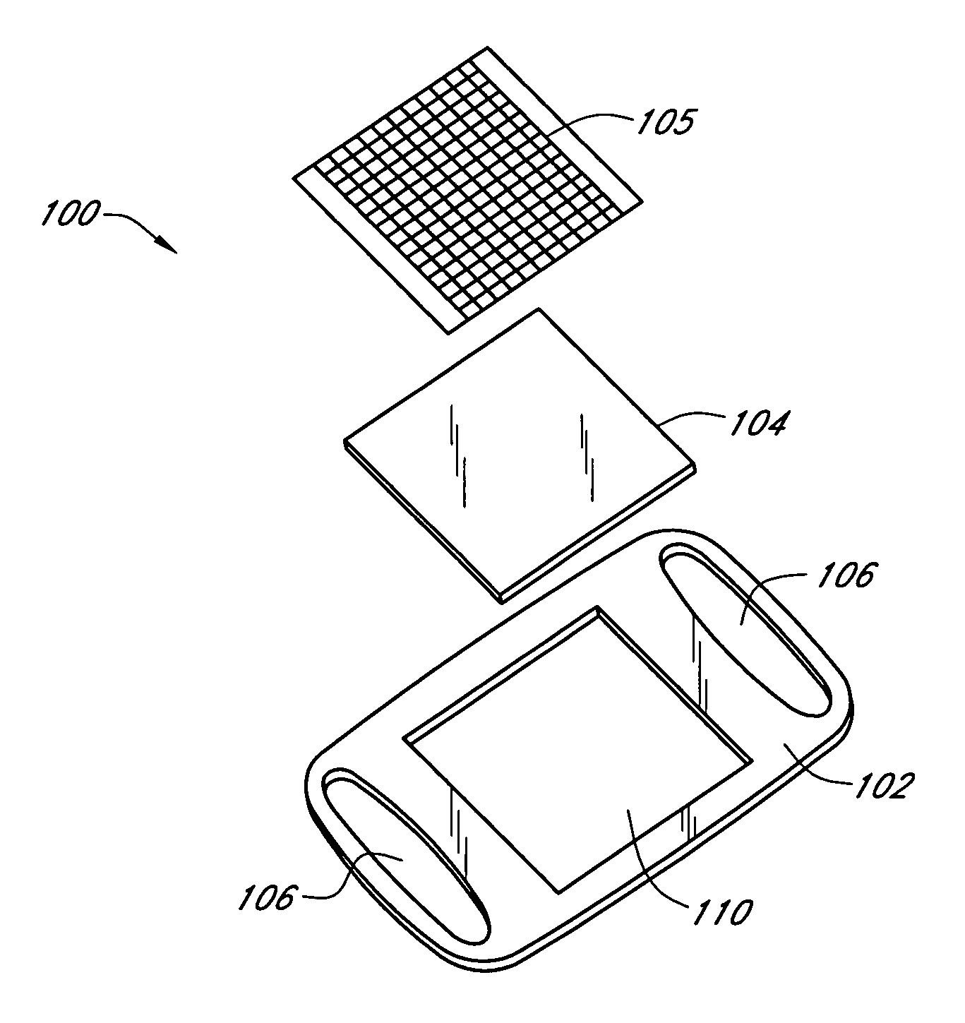
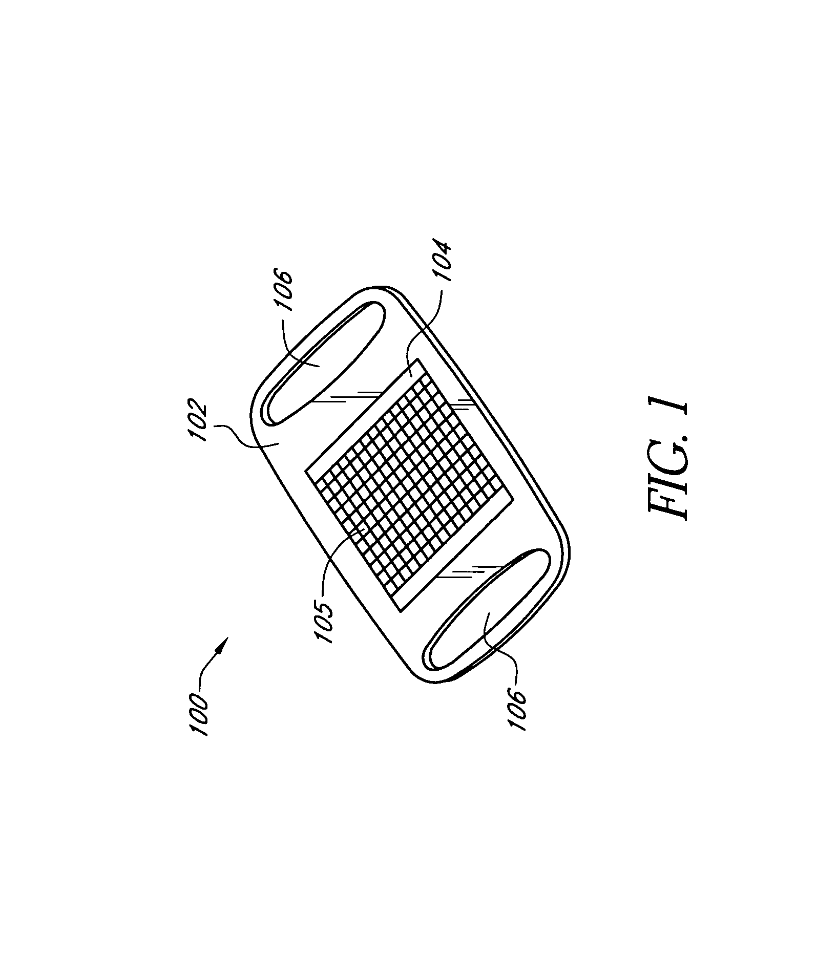
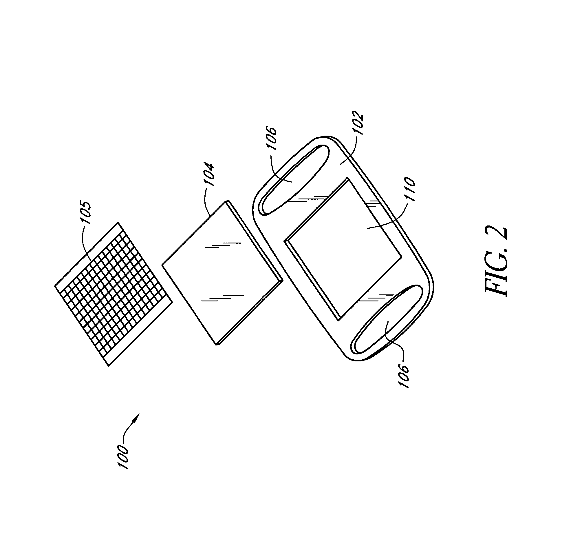
[0021]FIG. 1 is a perspective view of one embodiment of a wearable window 100. It is contemplated that the wearable window 100 is to be used in conjunction with a noninvasive optical measurement system such as, but not necessarily limited to, the apparatus taught in the above-mentioned U.S. Pat. No. 6,198,949. This patent discloses a noninvasive thermal gradient spectrometer comprising a window and a, thermal mass window, wherein the window forms an interface between a thermal mass window and a patient's skin. It is contemplated th...


PUM


Abstract

A device and method are provided for use with a noninvasive optical measurement system, such as a thermal gradient spectrometer, for improved determination of analyte concentrations within living tissue. In one embodiment, a wearable window is secured to a patient's forearm thereby isolating a measurement site on the patient's skin for determination of blood glucose levels. The wearable window effectively replaces a window of the spectrometer, and thus forms an interface between the patient's skin and a thermal mass window of the spectrometer. When the spectrometer must be temporarily removed from the patient's skin, such as to allow the patient mobility, the wearable window is left secured to the forearm so as to maintain a consistent measurement site on the skin. When the spectrometer is later reattached to the patient, the wearable window will again form an interface between the spectrometer and the same location of skin as before.

Description

RELATED APPLICATIONS[0001]This application claims the benefit of U.S. Provisional Patent Application No. 60 / 310,898, filed Aug. 8, 2001, entitled DEVICE FOR CAPTURING THERMAL SPECTRA FROM TISSUE, the entire contents of which are hereby incorporated by reference herein and made a part of this specification. In addition, this application is a continuation-in-part of U.S. patent application Ser. No. 09 / 760,423, filed Jan. 11, 2001, now U.S. Pat. No. 6,636,753, issued Oct. 21, 2003, titled SOLID-STATE NON-INVASIVE INFRARED ABSORPTION SPECTROMETER FOR THE GENERATION AND CAPTURE OF THERMAL GRADIENT SPECTRA FROM LIVING TISSUE, which is a continuation of U.S. patent application Ser. No. 09 / 265,195, filed Mar. 10, 1999, now U.S. Pat. No. 6,198,949, issued Mar, 6, 2001, titled SOLID-STATE NON-INVASIVE INFRARED ABSORPTION SPECTROMETER FOR THE GENERATION AND CAPTURE OF THERMAL GRADIENT SPECTRA FROM LIVING TISSUE.BACKGROUND OF THE INVENTION[0002]1. Field of the Invention[0003]This invention rela...

Claims


Application Information

Patent Timeline
IPC IPC(8): A61B5/00G01N21/31G01N21/35G01N21/01G01N21/03
CPCA61B5/01A61B5/061A61B5/14532G01J3/0286G01J3/0291G01N21/01A61B5/6824G01N2021/0389G01N2201/021G01N2201/0245G01N21/35
Inventor RULE, PETERBRAIG, JAMES R.GOLDBERGER, DANIEL S.CORTELLA, JULIAN M.SMITH, HEIDI M.HERRERA, ROGER O.WITTE, KENNETH G.HARTSTEIN, PHILIP C.AGOSTINO, MARK D.
Owner OPTISCAN BIOMEDICAL
Why Eureka
Try Eureka