Air conditioning system for a vehicle

a technology for air conditioning systems and vehicles, applied in the direction of machines, light and heating equipment, transportation and packaging, etc., can solve the problems of deteriorating the comfort of the vehicle, reducing the heating efficiency of the vehicle, and remarkably defrosting performan

Inactive Publication Date: 2005-11-01
HALLA CLIMATE CONTROL
View PDF28 Cites 22 Cited by
  • Summary
  • Abstract
  • Description
  • Claims
  • Application Information

AI Technical Summary

Benefits of technology

[0021]Accordingly the present invention has been made to solve the foregoing problems and it is an object of the present invention to provide a two-layer flow air conditioning system in which a partition wall is installed on a path between an evaporator and a heater core to divide internal air and external air, and a first temperature adjusting door and a second temperature adjusting door each having a fan shape are installed at both sides of the partition wall in such a manner as to be opened at their sides to control the flow direction of the internal air and the external air which are supplied to both sides of the partition wall so as to prevent any mixture between the internal air and the external air, thereby enhancing heating and cooling effects without degrading a defrosting performance.
[0023]Further, the temperature adjusting doors are installed in front and the rear of the heater core with compact constructions for guiding the cool and warm air to openings so that each air control mode can be simply performed.

Problems solved by technology

However, the conventional air conditioning unit for providing the two-layer airflow has the following problems.
This elevates the humidity of the external air to remarkably degrade the defrosting performance.
Further, this internal air leakage remarkably lowers a heating eff0ect.
In the meantime, the conventional two-layer air conditioning system simply supplies the internal / external air introduced into the air conditioning case 20 through the selected opening or vent but fails to simultaneously supply the cold air and the warm air which have respectively passed through the evaporator E and the heater core H, thereby deteriorating the comfort within the vehicle.

Method used


Image

  • Air conditioning system for a vehicle
  • Air conditioning system for a vehicle
  • Air conditioning system for a vehicle

Examples


Embodiment Construction

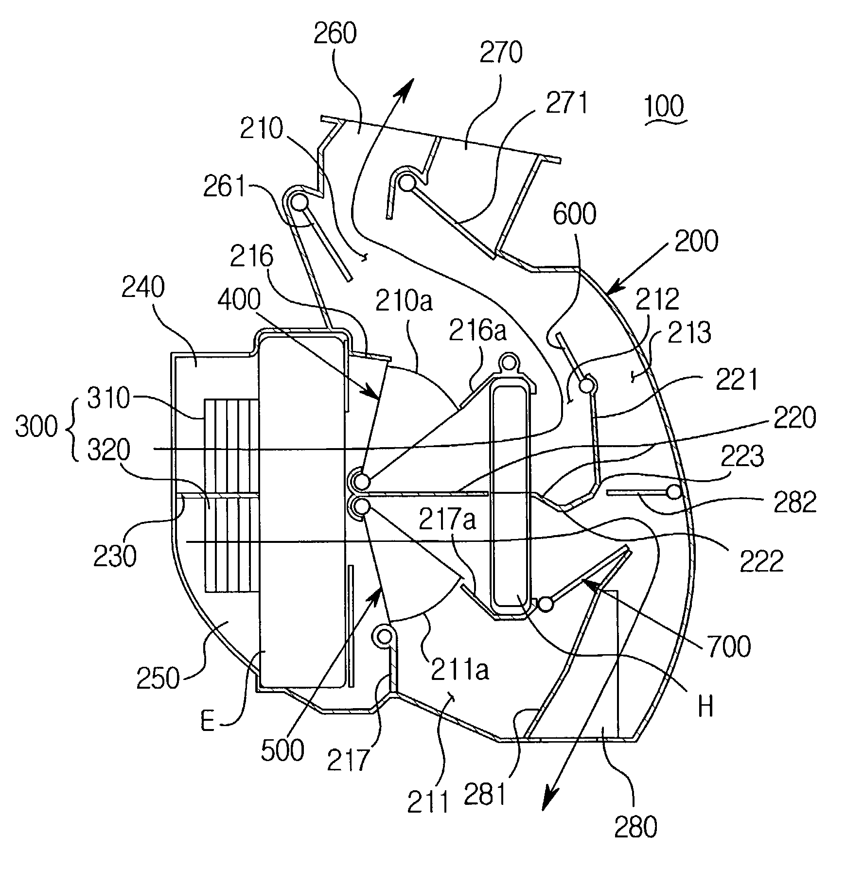
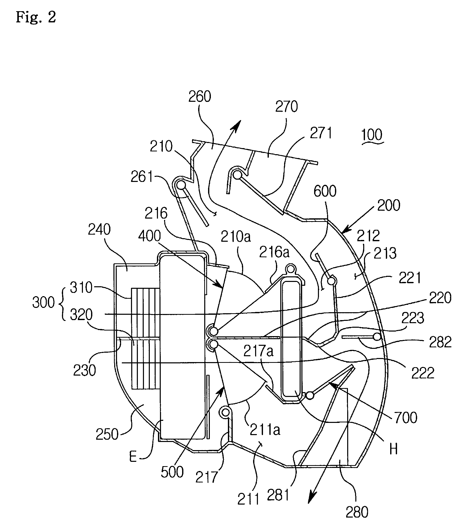
[0048]As shown in FIGS. 2 and 3, a two-layer flow air conditioning system 100 of the invention has a blower fan 300, which is installed on the entrance side of an air conditioning case 200 for forcibly blowing the air into a vehicle interior, and an evaporator E and a heater core H each installed in the rear of the blower fan in such a manner as to be spaced apart from each other by a certain interval.

[0049]The air conditioning case 200 has a partition wall 220 installed within the same for dividing the inside of the air conditioning case 200 into a first flow passage 210 functioning as an upper external air flow section and a second flow passage 211 functioning as a lower internal air flow section. Above and under the partition wall 220 in the rear of the heater core H, are respectively installed third and fourth temperature adjusting doors 600 and 700 which are separately operated to open / close the rear of the heater core H.

[0050]Further, the air conditioning case 200 has a partit...


PUM


Abstract

The present invention has been made to solve the foregoing problems and it is an object of the present invention to provide a two-layer flow air conditioning system in which a partition wall is installed on a path between an evaporator and a heater core to divide internal air and external air, and a first temperature adjusting door and a second temperature adjusting door each having a fan shape are installed at both sides of the partition wall in such a manner as to be opened at their sides to control the flow direction of the internal air and the external air which are supplied to both sides of the partition wall so as to prevent any mixture between the internal air and the external air, thereby enhancing heating and cooling effects without degrading a defrosting performance.It is another object of the invention to provide a two-layer flow air conditioning system in which a first temperature adjusting door and a second temperature adjusting door is operated separately and a horizontal partition wall extends from the rearward of the evaporator to the rearward of a heater core via the heater core so that the cool and warm air having different properties is circulated through separate passages to supply the warm air to the vehicle interior and supply the cool air to a windshield for defrosting or to supply the cool air to the vehicle interior and supply the warm air is supplied to the windshield.

Description

BACKGROUND OF THE INVENTION[0001]1. Field of the Invention[0002]The present invention relates to an air conditioning system for vehicles, and more particularly, to a two-layer flow air conditioning system capable of separately blowing internal and external air.[0003]2. Background of the Related Art[0004]Generally in heating a vehicle interior in winter, cold and dry external air is introduced in order to prevent any frost on a windshield, which results in a corresponding decrease in the temperature of the vehicle interior.[0005]In order to solve the above problem, an air conditioning unit is developed to provide two-layer airflow. Such an air conditioning unit realizes two-layer flow of the internal / external air by providing the external air to an upper region of the vehicle interior and circulating the internal air through a lower region of the vehicle interior. The fresh and dry external air provided to the upper region reduces the frost occurring on the windshield to ensure a def...

Claims


Application Information

Patent Timeline
Patent Type & Authority Patents(United States)
IPC IPC(8): B60H1/00
CPCB60H1/00064B60H1/00685B60H2001/00135B60H2001/00164B60H1/00
Inventor LEE, JUNKANGPARK, CHANGHOHAN, INCHULYOO, SUNJAE
Owner HALLA CLIMATE CONTROL
Why Eureka
Try Eureka