Device for cooling a bearing; flywheel energy storage system using such a bearing cooling device and methods related thereto

a technology for cooling devices and bearings, which is applied in the field of flywheel energy storage systems, can solve the problems of reducing the vacuum during operation, and the heat dissipation technique is not compatible with flexible bearing mounting arrangements, and achieves the effect of dissipating heat energy

Inactive Publication Date: 2005-11-01
BEACON POWER LLC
View PDF10 Cites 36 Cited by
  • Summary
  • Abstract
  • Description
  • Claims
  • Application Information

AI Technical Summary

Problems solved by technology

The materials that make up the flywheel system, however, may entrain or evolve substantial quantities of materials that may be released within the system when under a vacuum, thus causing a reduction of the vacuum during operation.
Such a heat dissipation technique, however, is not compatible with flexible bearing mounting arrangements.

Method used


Image

  • Device for cooling a bearing; flywheel energy storage system using such a bearing cooling device and methods related thereto
  • Device for cooling a bearing; flywheel energy storage system using such a bearing cooling device and methods related thereto
  • Device for cooling a bearing; flywheel energy storage system using such a bearing cooling device and methods related thereto

Examples


Embodiment Construction

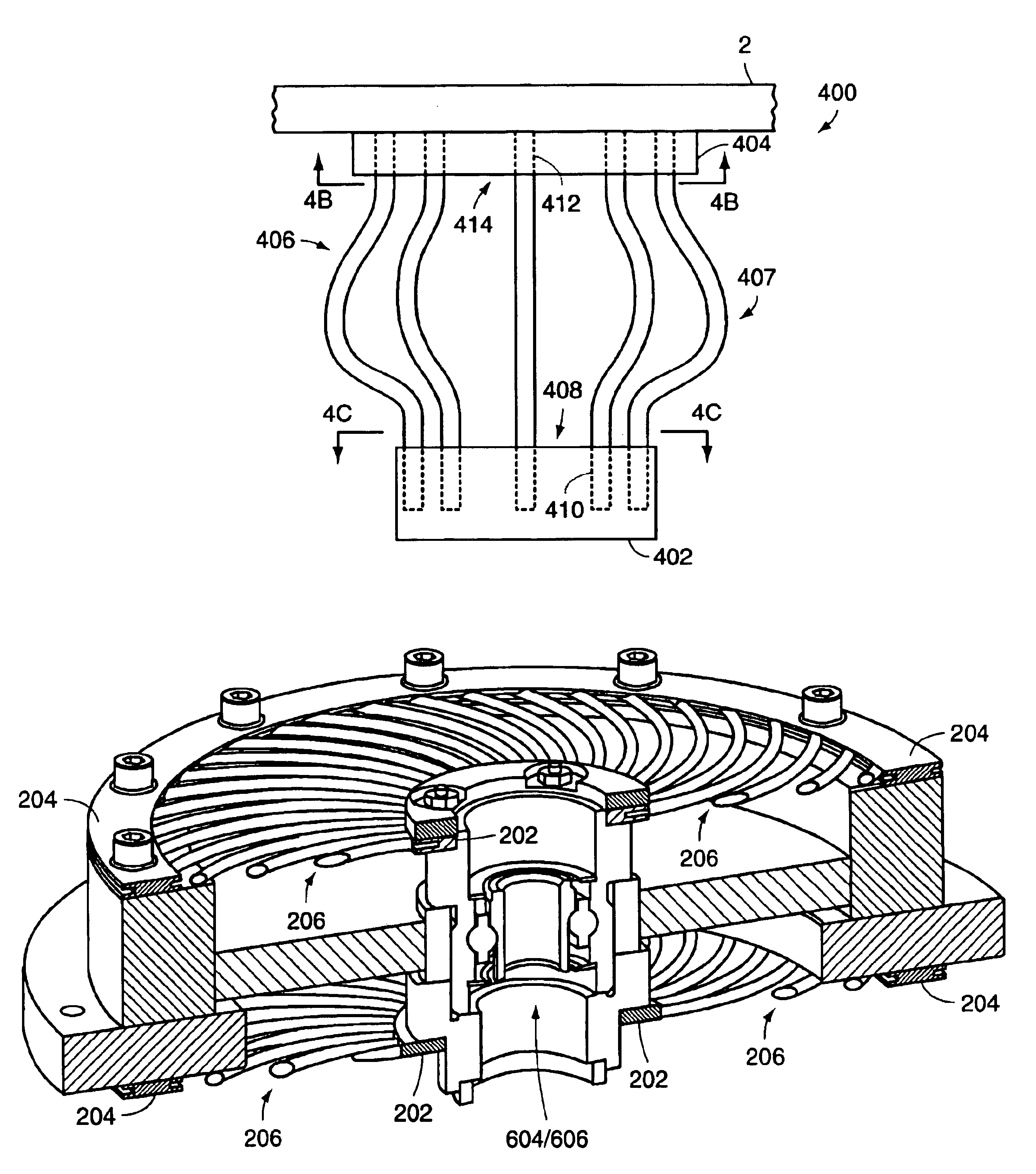
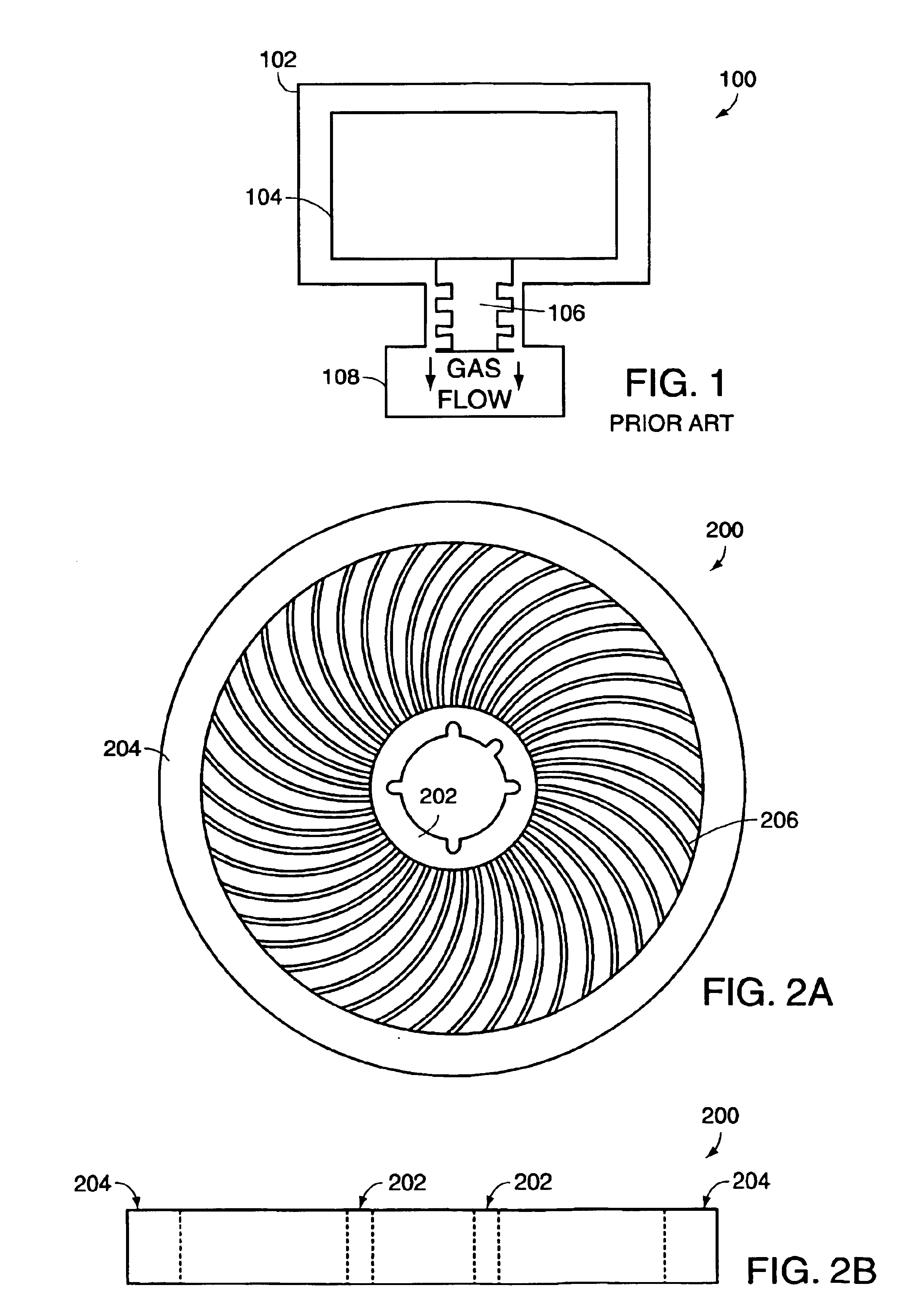
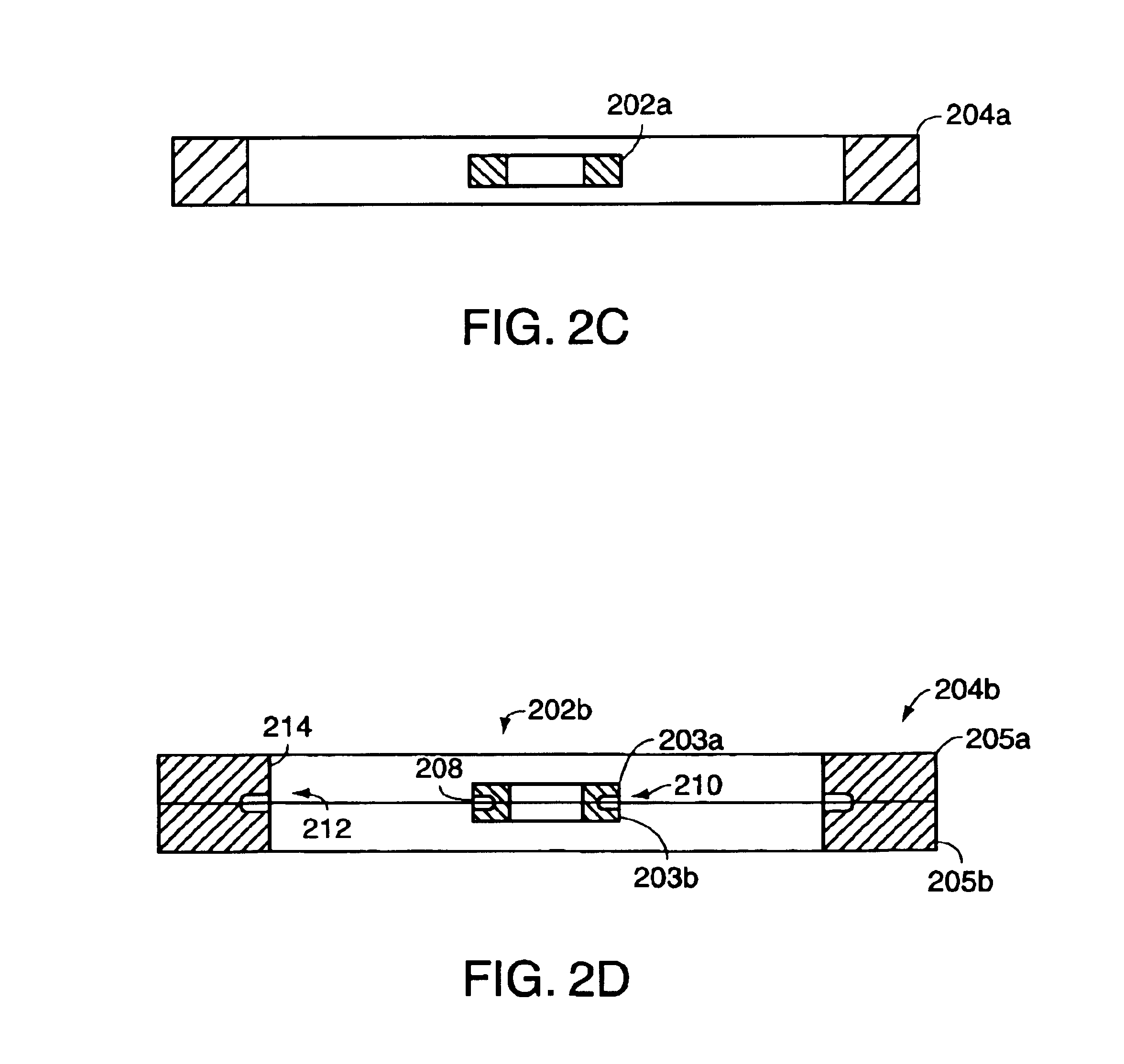
[0045]Referring now to the various figures of the drawing wherein like reference characters refer to like parts, there is shown in FIGS. 2A, B a plan and side view respectively of a heat transferring assembly 200 according to one aspect of the present invention. The heat transferring assembly 200 includes an inner member 202, an outer member 204 and one or more, a plurality, or more particularly a multiplicity, of intermediate members 206. The inner, outer and intermediate members 202-206 are each generally composed, at least in part, of a material that can receive and transfer heat energy, for example by conduction, and which are arranged and configured such that heat energy generated by a component, functionality, member or the like of an apparatus / system and being received by the inner member 202 is communicated to the outer member 204 by each of the one or more / plurality / multiplicity of intermediate members 206 and so that the heat energy being received by the outer member 204 f...


PUM


Abstract

Featured is a heat transferring device being configured and arranged so that at least some of the heat energy being generated by a heat producing device, such as the a bearing assembly of a flywheel energy storage system, is communicated directly from the locus of the device directly to a heat sink structure remote from the locus of the device. The heat-transferring device includes one or more flexible thermally conductive members, one end of each being thermally coupled to the heat generating device and the other end of each being thermally coupled to the heat sink. The flexible member also is configured and arranged so as to allow relative motion between the heat generating device and the heat sink in or about one or more directions or axes. The heat-transferring device further includes first and second conductive members that are each configured and arranged to thermally couple each flexible member end to one of the heat producing device and the heat sink.

Description

FIELD OF INVENTION[0001]The present invention relates generally to flywheel energy storage systems, and more particularly to devices and methods for cooling bearings and other heat producing mechanisms utilized in flywheel energy storage systems, which systems use a vacuum environment to reduce windage losses.BACKGROUND OF THE INVENTION[0002]The ability of flywheels to accept and release energy over relatively short time periods has been known for many years and energy storage flywheels have been used, or proposed for use, in a variety of applications. Such proposed and actual use applications include motor vehicle applications and stand alone supplemental energy sources.[0003]There is shown in FIG. 1 a simplified view of a conventional flywheel energy storage system 100 used for storing kinetic energy. The conventional flywheel system 100 includes a flywheel assembly 104 disposed in a flywheel housing 102. Further, the flywheel housing is configured and arranged so such flywheel as...

Claims


Application Information

Patent Timeline
Patent Type & Authority Patents(United States)
IPC IPC(8): F16C37/00F28D15/02H02K5/173H02K9/22H02K7/02H02K7/00
CPCF16C37/00F28D15/0208H02K5/1732H02K9/22H02K7/02F16C2360/45H02K9/227H02K9/223
Inventor WOODARD, NATHAN G.KABIR, OMAR M.RATHBUN, JEREMIAH I.
Owner BEACON POWER LLC
Why Eureka
Try Eureka