Transmission mount structure for vehicles

a technology for transmission mounts and vehicles, applied in the direction of machine supports, shock absorbers, jet propulsion mountings, etc., can solve the problems of difficult to achieve a good combination of the spring constant in the vertical direction, and the mount member no longer is possibl

Inactive Publication Date: 2005-11-01
HONDA MOTOR CO LTD
View PDF8 Cites 12 Cited by
  • Summary
  • Abstract
  • Description
  • Claims
  • Application Information

AI Technical Summary

Benefits of technology

[0007]According to the present invention, there is provided a transmission mount structure for mounting a transmission connected to an end of a transverse-mounted engine to a vehicle body, comprising an elastic main vibration-damping member for reducing both vibrations in a vertical direction and vibrations in a roll direction, and an elastic auxiliary vibration-damping member smaller in diameter or thickness than the main vibration-damping member and extending in a direction substantially perpendicular to the roll direction, the auxiliary vibration-damping member having a constricted portion at a longitudinal central portion thereof, the constricted portion having a smaller cross-section than any other part of the auxiliary vibration-damping member.

Problems solved by technology

However, since the spring constant in the roll direction of the elastic vibration isolator also increases with an increase in the horizontal cross-sectional area of the same elastic vibration isolator, it is no longer possible for the mount member 107 to effectively reduce vibrations and displacement in the roll direction.
Thus, it is difficult to achieve a good combination of the spring constant in the vertical direction with the spring constant in the roll direction.

Method used


Image

  • Transmission mount structure for vehicles
  • Transmission mount structure for vehicles
  • Transmission mount structure for vehicles

Examples


Embodiment Construction

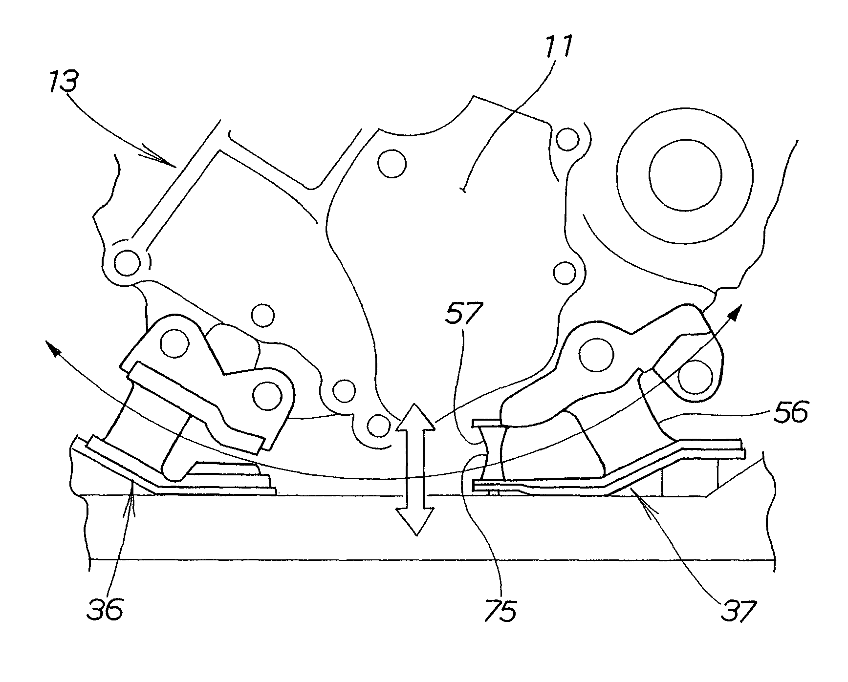
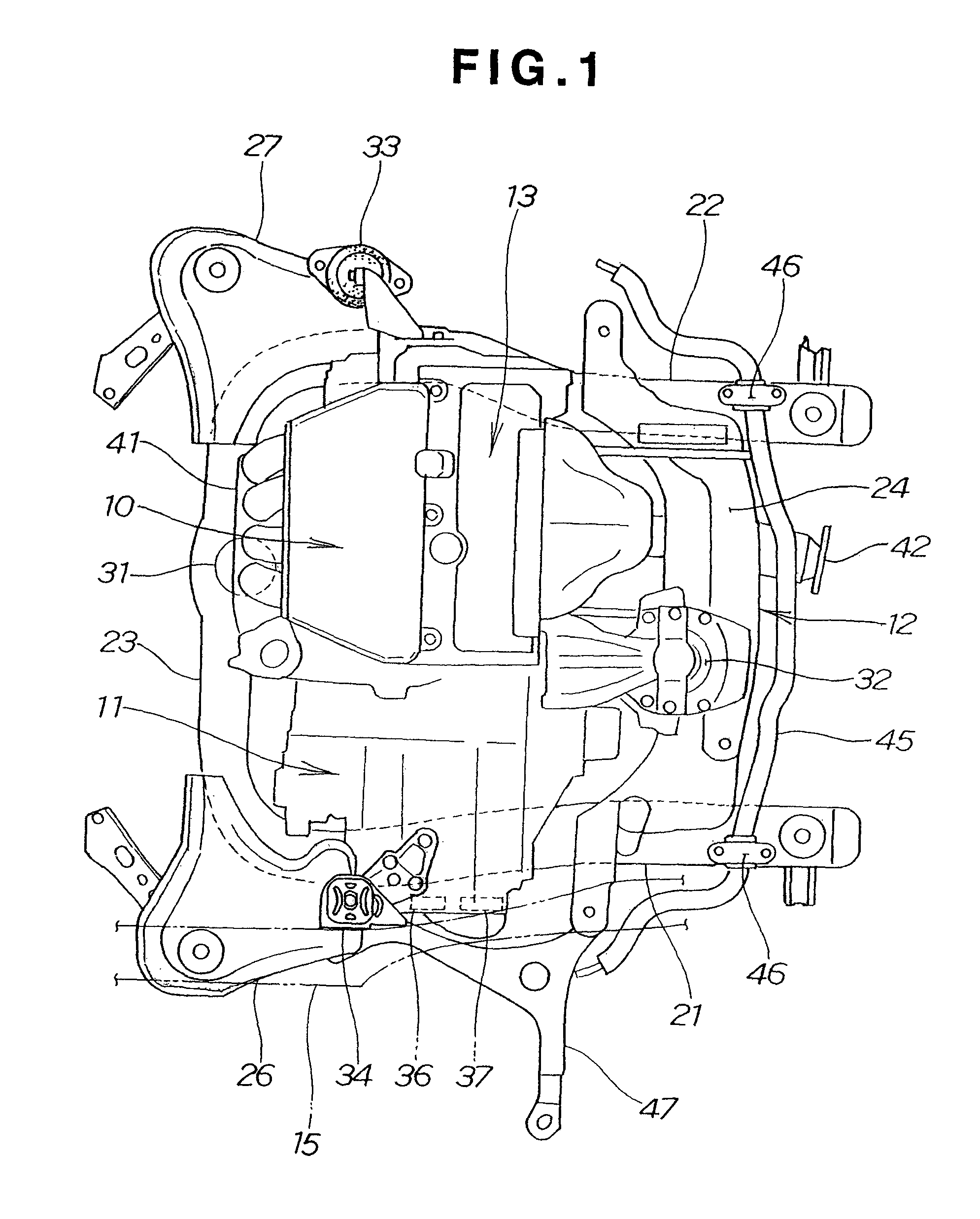
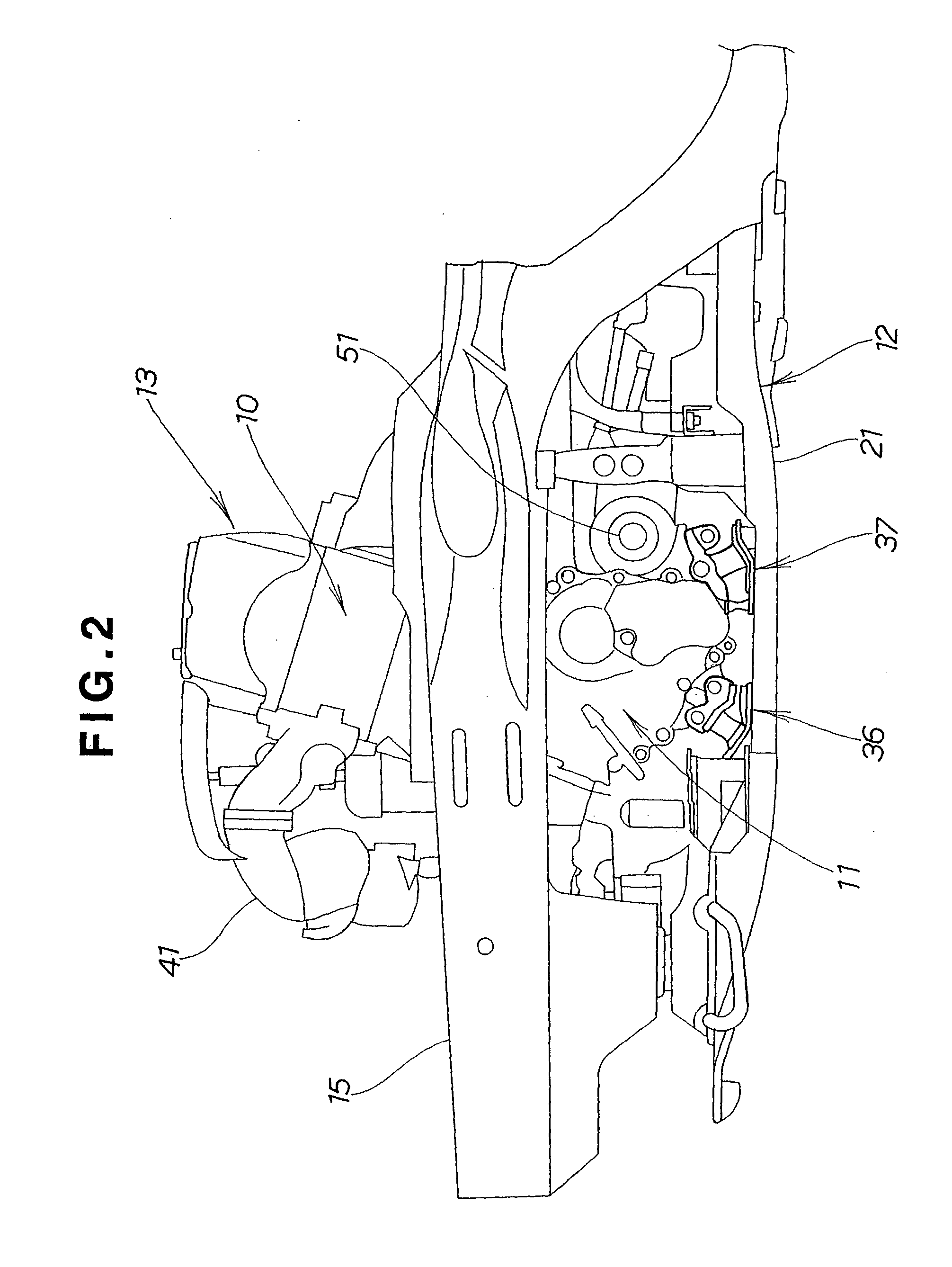
[0020]Referring now to the drawings and FIG. 1 in particular, there is shown in plan view the interior of a vehicular engine room in which a power unit 13 is installed using a mount system including a transmission mount structure according to the present invention. The power unit 13 of the vehicle is comprised of a transverse-mounted engine 10 and a transmission 11 connected or integrally assembled with an output end of the engine 10. Though not shown, the engine 10 has a crankshaft extending in a transverse direction of the vehicle. The engine 10 and transmission 11 thus assembled are supported by a sub-frame 12 and right and left front side frames (only the left front side frame being shown and designated by numeral 15).

[0021]The sub-frame 12 is an assembly formed jointly by left and right longitudinal sub-frame members 21 and 22 extending in a longitudinal or front-to-rear direction of the vehicle, front and rear crossbeams 23 and 24 connecting the longitudinal sub-frame members ...


PUM

PropertyMeasurementUnit
diameteraaaaaaaaaa
thicknessaaaaaaaaaa
vibration-dampingaaaaaaaaaa

Abstract

A transmission mount structure for mounting a transmission connected to an end of a transverse-mounted engine to a vehicle body includes an elastic main vibration-damping member for reducing both vibrations in a vertical direction and vibrations in a roll direction, and an elastic auxiliary vibration-damping member smaller in diameter or thickness than the main vibration-damping member and extending in a direction substantially perpendicular to the roll direction. The auxiliary vibration-damping member has a constricted portion formed at a longitudinal central portion thereof and having a smaller cross-section than any other part of the auxiliary vibration-damping member.

Description

FIELD OF THE INVENTION[0001]The present invention relates to an improvement in a transmission mount structure for vehicles.BACKGROUND OF THE INVENTION[0002]Various transmission mount structures for vehicles are known, wherein a transmission is supported at a single point while an engine, which forms together with the transmission a vehicle power unit, is supported at two points. One example of such known transmission mount structures is disclosed in Japanese Patent Laid-Open Publication HEI-10-309945.[0003]The disclosed transmission mount structure, as illustrated here in FIG. 7, includes a mount member 107 attached at one end to a mount bracket 103 connected to an end of a transmission 101 and, at the other end, to a mount bracket 108 connected to a chassis frame 104 of a vehicle. The transmission 101 is connected to an output end of a transverse-mounted engine 100. A mount member 105 is connected to a front end portion of the engine 100 via a mount bracket 102 and also connected t...

Claims


Application Information

Patent Timeline
Patent Type & Authority Patents(United States)
IPC IPC(8): B60K5/04B60K5/00B60K5/12B60K17/06F16F1/373F16F1/44
CPCB60K5/04B60K5/1208B60K5/1216F16F1/373F16F1/44
Inventor MIYAHARA, TETSUYA
Owner HONDA MOTOR CO LTD
Why Eureka
Try Eureka