Seal for a compressor and centrifugal compressor equipped with such a seal

a technology for centrifugal compressors and seals, which is applied in the direction of mechanical equipment, non-positive displacement pumps, liquid fuel engines, etc., can solve the problems of sealing being subjected to high thermal loading, loss of sealing, and even destruction of hardwar

Inactive Publication Date: 2005-11-01
THERMODYN
View PDF15 Cites 69 Cited by
  • Summary
  • Abstract
  • Description
  • Claims
  • Application Information

AI Technical Summary

Benefits of technology

[0017]It is therefore possible to envisage heating the flui

Problems solved by technology

When the compressor is operating, the seals are subjected to high thermal loadings due, in particular, to the temperature of the fluid passing through the compressor, to the expansion of the fluid at the seal, to the shear of the film of fluid at the sealing interface between the respective friction faces of the rotating and stationary seal face rings, and to the ventilation losses brought about as the rotating seal face ring rotates through the fluid conveyed by the compressor.
It is known that these thermal loadings generate deformation at the rotating seal face ring and the stationary seal face ring as a result of differential expansion, and this carries the risk of leading to a loss of sealing or even to

Method used


Image

  • Seal for a compressor and centrifugal compressor equipped with such a seal
  • Seal for a compressor and centrifugal compressor equipped with such a seal
  • Seal for a compressor and centrifugal compressor equipped with such a seal

Examples


Embodiment Construction

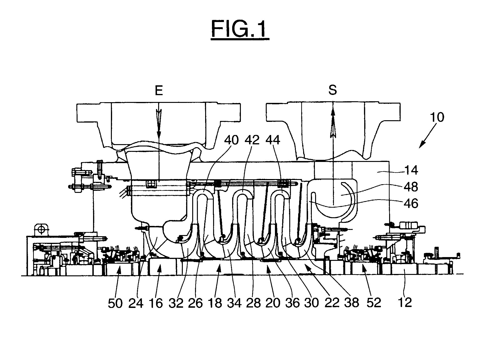
[0028]FIG. 1 depicts the overall structure of a centrifugal compressor, denoted by the general numerical reference 10.

[0029]It is intended for handling a compressible fluid and its purpose is to transfer mechanical energy to this fluid so as to increase its pressure.

[0030]In the example depicted, the compressor 10 consists of a multi-cell compressor, that is to say a multi-stage compressor. The compressor 10 actually has four compression stages.

[0031]It essentially comprises a drive shaft 12 driven in rotation by appropriate drive means and rotating in a casing 14.

[0032]This casing 14 is provided with an inlet E for the intake of compressible fluid, communicating with a supply source appropriate to the envisaged use, and with an outlet S for distributing the compressed fluid.

[0033]Between the inlet E and the outlet S the casing 14 is provided with the four compression stages 16, 18, 20 and 22.

[0034]Each stage 16, 18, 20 and 22 comprises, from the upstream end downstream, considering...


PUM


Abstract

A seal for a rotary compressor comprises a casing, at least one assembly having a rotating seal face ring which rotates as one with a sleeve intended to be mounted on a shaft of the compressor and of a stationary seal face ring mounted on the casing, the seal face rings being urged to press against one another via their rubbing face. The seal design further incorporates fluid circulation for heating leaks of compressible fluid conveyed by the compressor that occur between the seal face rings, this fluid circulation being formed in the casing and extending at least partially downstream of the seal face rings with respect to the direction of flow of the fluid stream.

Description

BACKGROUND OF THE INVENTION[0001]The present invention relates to a seal for a rotary compressor and to a compressor provided with such a seal.DESCRIPTION OF RELATED ART[0002]Rotary compressors are rotary machines intended to convey compressible fluids, and their purpose is to transfer mechanical energy to the fluid which passes through them with a view to increasing its pressure.[0003]To this end they comprise a drive shaft which drives the rotation of a collection of wheels which mainly transmit to the fluid the mechanical energy supplied by the motor that drives the shaft.[0004]With a view to containing the pressurized fluid within the body of the compressor, the ends of the shaft are provided with dry seals with sealing gas.[0005]Such seals are conventionally provided with a casing, with a stationary seal face ring or gland washer mounted on the casing and with a rotating seal face ring which rotates as one seal sleeve mounted on the drive shaft of the compressor, these seal fac...

Claims


Application Information

Patent Timeline
IPC IPC(8): F04D29/08F04D29/12F04D29/58F16J15/34
CPCF04D29/122F04D29/584F16J15/3404F16J15/3468F04D17/122
Inventor PUGNET, JEAN-MARCBOLUSSET, DANIELFRIEZ, PATRICK
Owner THERMODYN
Why Eureka
Try Eureka