Direct-type back light device

a back light device and direct-type technology, applied in the direction of light sources, instruments, electrical equipment, etc., can solve the problems of type back light, difference between the boosting voltage of the inverter, manufacture of the inverter, etc., to achieve equalizing the capacitance of the capacitor, maintaining uniform luminance, and boosting voltages

Inactive Publication Date: 2005-11-01
LS TECH
View PDF8 Cites 20 Cited by
  • Summary
  • Abstract
  • Description
  • Claims
  • Application Information

AI Technical Summary

Benefits of technology

[0013]Accordingly, the present invention has been made keeping in mind the above problems occurring in the prior art, and an object of the present invention is to provide a direct-type back light device which is constructed so that a plurality of fluorescent lamps are connected to a single invert in parallel with each other by a capacitive circuit element, thus boosting voltages supplied to the fluorescent lamps in the same boosting ratio and thereby equalizing capacitance of a capacitor, therefore maintaining uniform luminance.
[0014]Another object of the present invention is to provide a direct-type back light device which is constructed so that a plurality of fluorescent lamps are turned on or off using a single inverter, thus reducing manufacturing costs and power consumption.
[0015]A further object of the present invention is to provide a direct-type back light device which is constructed so that leads extending from both ends of each of fluorescent lamps are directly connected to an independent electrode and a common electrode which are provided on the both ends of the fluorescent lamp, thus being easy to handle the leads. Further, the direct-type back light device uses a single inverter, thus being easy to assemble and reducing costs of the product.

Problems solved by technology

However, because the conventional direct-type back light device is constructed so that the plurality of inverters are connected to the plurality of fluorescent lamps in series, the conventional direct-type back light device has a problem as follows.
The conventional direct-type back light device has a problem in that it is impossible to manufacture the inverters connected to the fluorescent lamps in series so that the transformers provided in the inverters have the same boosting ratio, thus there exists difference between the boosting voltages of the inverters.
Due to such difference of the boosting voltages, electrostatic capacities of the capacitors are different from each other, thus reducing uniformity of the luminance of the back light device.
The conventional direct-type back light device has another problem in that the number of the inverters is increased as the number of the fluorescent lamps is increased, in case where the inverters are connected to the fluorescent lamps in series, thus increasing manufacturing costs, and increasing power consumption due to the use of a large number of inverters.
The conventional direct-type back light device has a further problem in that a large number of inverters are mounted to a lower surface of the reflection member, so that it is difficult to handle leads which connect the inverters to the fluorescent lamps and thereby it is difficult to assemble the product.
Recently, because a large-sized LCD has been developed, the above-mentioned problems become more serious.

Method used


Image

  • Direct-type back light device
  • Direct-type back light device
  • Direct-type back light device

Examples


Embodiment Construction

[0033]Hereinafter, embodiments of the present invention will be described in detail with reference to the attached drawings.

[0034]Reference now should be made to the drawings, in which the same reference numerals are used throughout the different drawings to designate the same or similar components.

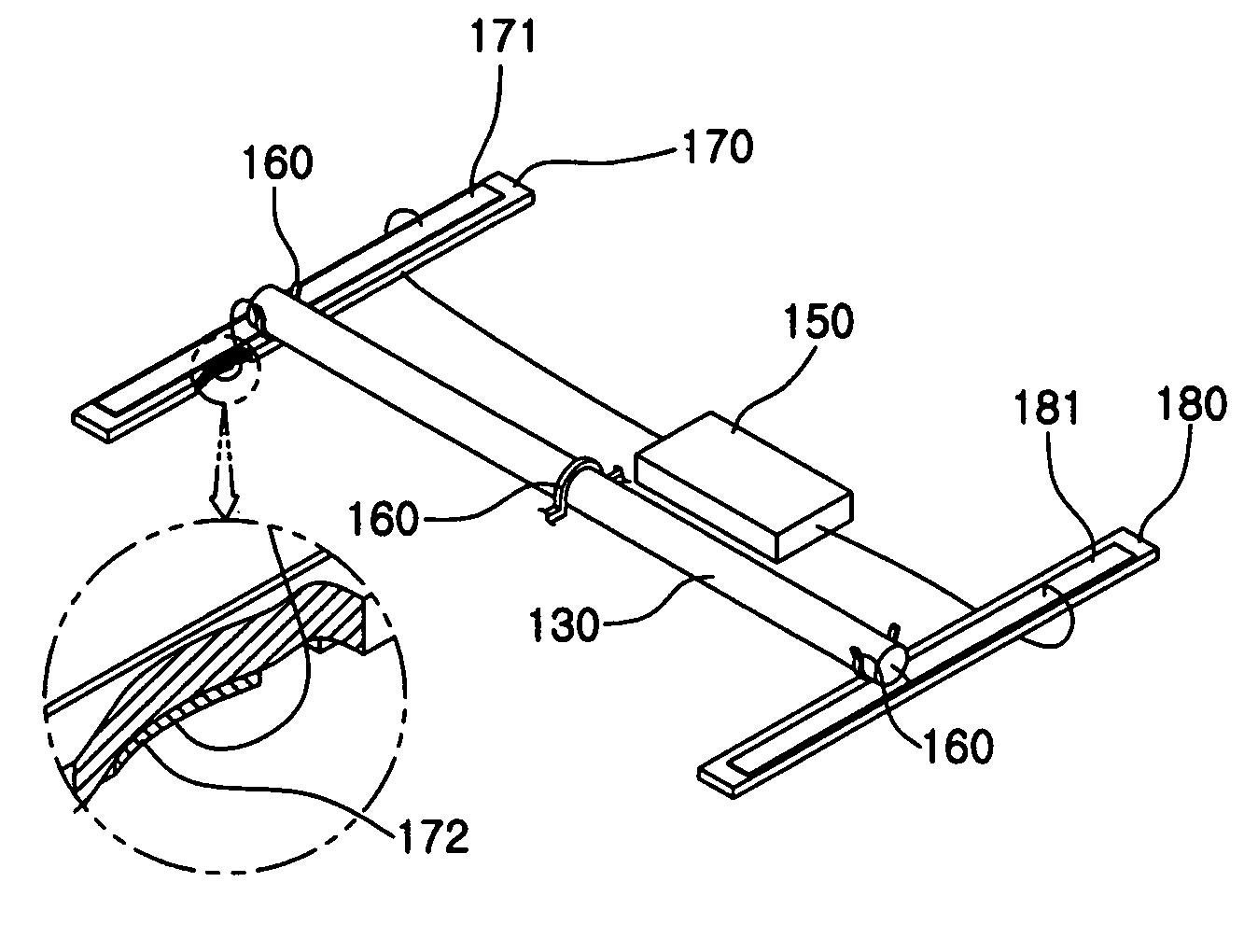
[0035]FIG. 3 is a perspective view of a direct-type back light device, according to the present invention. FIGS. 4a and 4b are views to show two different parallel connections of a plurality of fluorescent lamps and a single inverter which are included in the direct-type back light device of FIG. 3. FIGS. 5a and 5b are equivalent circuit diagrams corresponding to FIGS. 4a and 4b, respectively. FIG. 6a is a perspective view to show a parallel connection of the plurality of fluorescent lamps and the single inverter which are included in the direct-type back light device of FIG. 3.

[0036]Referring to FIGS. 3, 4a, 4b, 5a, 5b, and 6a, the back light device of this invention includes a frame 110...


PUM

PropertyMeasurementUnit
outer diameteraaaaaaaaaa
lengthaaaaaaaaaa
shapeaaaaaaaaaa

Abstract

The object of this invention is to provide a direct-type back light device, capable of maintaining uniform luminance, and reducing manufacturing costs and power consumption, in addition to being easy to assemble and to accomplish thinness. The back light device includes a frame, a diffusion member provided in an upper portion of the frame to diffuse light, a plurality of fluorescent lamps provided under the diffusion member to radiate the light, a reflection member provided under the plurality of fluorescent lamps to reflect the light radiated from the fluorescent lamps, a lamp holder to hold each of the plurality of fluorescent lamps, an inverter to turn on or off the plurality of fluorescent lamps, and a capacitive circuit element and an insulator provided on first and second ends of the fluorescent lamps, respectively, to connect the plurality of the fluorescent lamps to the inverter in parallel with each other. The capacitive circuit element includes along a first surface thereof a first common electrode to be connected to a first end of the inverter, and a plurality of independent electrodes along a second surface thereof to be connected to the first ends of the fluorescent lamps. The insulator has along a surface thereof a second common electrode to be connected to the second end of each of the fluorescent lamps and to a second end of the inverter.

Description

BACKGROUND OF THE INVENTION[0001]1. Field of the Invention[0002]The present invention relates generally to direct-type back light devices, and more particularly, to a direct-type back light device, which is capable of maintaining uniform luminance, and reducing manufacturing costs and power consumption, in addition to being easy to assemble and to accomplish thinness.[0003]2. Description of the Related Art[0004]A liquid crystal display (LCD) is an electric element which converts several electric signals indicative of information produced from various units into visual signals using a transmittance of liquid crystal which is changed in response to an applied voltage, prior to transmitting visual information to a person. Since the LCD itself cannot emit light to produce images, the LCD must be provided with a back light device. The images are produced on the LCD by light radiated from the back light device.[0005]There is a growing tendency for a back light device which has high and un...

Claims


Application Information

Patent Timeline
Patent Type & Authority Patents(United States)
IPC IPC(8): H05B41/282H05B41/28G02F1/13357
CPCH05B41/2822G02F1/133604G02F1/1335
Inventor PARK, DEUK ILRHEW, CHOONG YOP
Owner LS TECH
Why Eureka
Try Eureka