Poly-Insulator-Poly Capacitor and Fabrication Method for Making the Same

Inactive Publication Date: 2007-10-11
UNITED MICROELECTRONICS CORP
View PDF2 Cites 16 Cited by
  • Summary
  • Abstract
  • Description
  • Claims
  • Application Information

AI Technical Summary

Benefits of technology

[0016] Preferably, by forming two dielectric layers between three polysilicon layers, the present invention is able to provide a PIP capacitor having doubled capacitance per unit capacitor while significantly reducing the area of the capacitor. Despite the capacitance of the capacitor is doubled, the number of photomasks utilized during the fabrication process is not increased while comparing to the prior art. Ultimately, by increasing the capacitance density of the capacitor while reducing the area needed for fabrication, the present invention is able to significantly increase the yield and overall production of the product.

Problems solved by technology

However, the capacitance density of the above-mentioned prior art structure becomes insufficient as the demand for capacitors with high capacity increases.
In order to increase the capacitance of the capacitor, the area of the electrodes or the distance between the electrodes of the PIP capacitor structure must be significantly increased, thereby increasing the size of the capacitor and the complexity of the fabrication process.

Method used


Image

  • Poly-Insulator-Poly Capacitor and Fabrication Method for Making the Same
  • Poly-Insulator-Poly Capacitor and Fabrication Method for Making the Same
  • Poly-Insulator-Poly Capacitor and Fabrication Method for Making the Same

Examples


Embodiment Construction

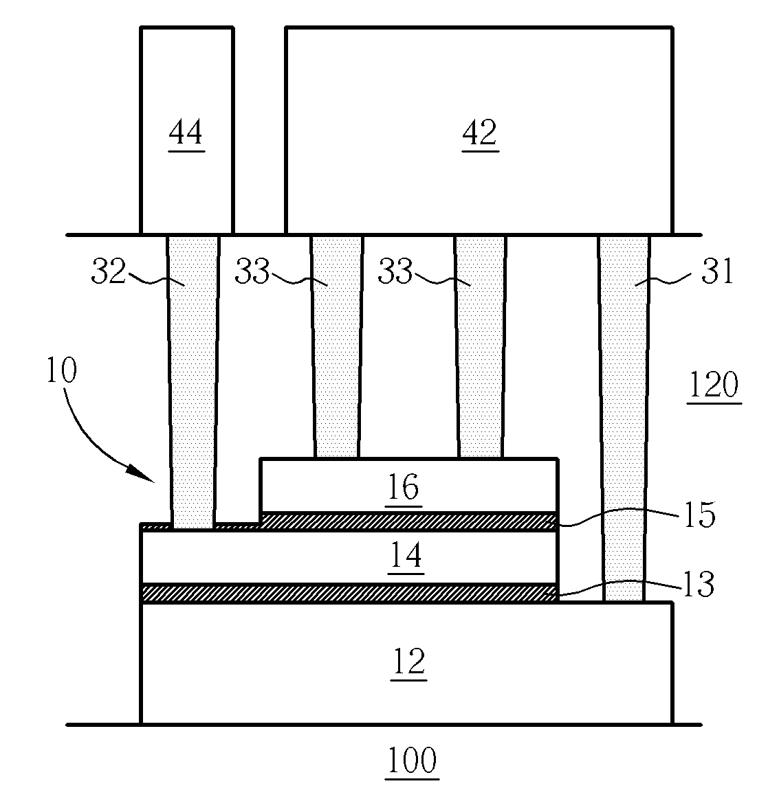
[0021] Please refer to FIG. 3. FIG. 3 is a perspective diagram illustrating a PIP capacitor 10 according to a preferred embodiment of the present invention. As shown in FIG. 3, the PIP capacitor 10 includes a first polysilicon plate 12, which maybe defined on a base layer 100 such as an interpoly dielectric layer, but not limited thereto. A second polysilicon plate 14, which is thinner than the first polysilicon plate 12, is stacked above the first polysilicon plate 12 and is electrically isolated from the first polysilicon plate 12 with a first capacitor dielectric layer 13. A third polysilicon plate 16 is stacked above the second polysilicon plate 14 and is electrically isolated from the second polysilicon plate 14 with a second capacitor dielectric layer 15. Preferably, the first polysilicon plate 12 is composed of a polysilicon layer or a combination of a polysilicon layer and a polycide layer, such as a tungsten silicide (WSi) layer. The second polysilicon plate 14 is composed ...


PUM


Abstract

A poly-insulator-poly (PIP) capacitor includes a first polysilicon plate; a first capacitor dielectric layer disposed on the first polysilicon plate; a second polysilicon plate stacked on the first capacitor dielectric layer, wherein the first polysilicon plate, the first capacitor dielectric layer, and the second polysilicon plate constitute a lower capacitor; a second capacitor dielectric layer disposed on the second polysilicon plate; and a third polysilicon plate stacked on the second capacitor dielectric layer, wherein the second polysilicon plate, the second capacitor dielectric layer, and the third polysilicon plate constitute an upper capacitor. Preferably, the first polysilicon plate and the third polysilicon plate are electrically connected to a first terminal of the PIP capacitor, while the second polysilicon plate is electrically connected to a second terminal of the PIP capacitor.

Description

BACKGROUND OF THE INVENTION [0001] 1. Field of the Invention [0002] The present invention relates to a poly-insulator-poly (PIP) capacitor, and more particularly, to a PIP capacitor having high capacitance density and fabrication method for making the same. [0003] 2. Description of the Prior Art [0004] Capacitors are elements that are used extensively in semiconductor devices for storing an electrical charge. Capacitors essentially comprise two conductive electrodes separated by an insulator. The capacitance, or amount of charge held by the capacitor per applied voltage, depends on a number of parameters such as the area of the electrodes, the distance between the electrodes, and the dielectric constant value for the insulator between the electrodes, as examples. [0005] It is common for capacitors, as well as resistors, transistors, diodes, and other circuit elements, to be formed in semiconductor integrated circuits (IC's) of various types. Capacitors formed within analog integrate...

Claims


Application Information

Patent Timeline
IPC IPC(8): H01L27/108H01L29/94H01L29/76H01L31/119
CPCH01L21/76838H01L28/60H01L27/0629
Inventor KAO, CHING-HUNG
Owner UNITED MICROELECTRONICS CORP
Why Eureka
Try Eureka