
Image display control system reducing image transmission delay

a control system and image technology, applied in the field of video display control methods and video display control systems, can solve the problems of poor camera operability, data transmission delay is prone to be caused by data transmission, and the amount of data to be transmitted becomes large for the network bandwidth, so as to reduce the transmission delay

Inactive Publication Date: 2005-11-01
FUJITSU LTD
View PDF6 Cites 13 Cited by
  • Summary
  • Abstract
  • Description
  • Claims
  • Application Information

AI Technical Summary

Benefits of technology

[0008]It is a general object of the present invention to provide a video display control method, a video display control system, and apparatuses forming such a system in which the above-described disadvantage is eliminated.
[0009]A more specific object of the present invention is to provide a video display control method and a video display control system that allow a user to be quickly presented with video obtained as a result of camera control and that can perform camera control without stress on a low-speed line, and apparatuses forming such a system.
[0012]According to the above-described method and system, the data of the video transmitted via the network is processed based on the camera operation information transmitted via the network. Therefore, the image of the video can be displayed to a user with a reduced transmission delay, and the camera can be controlled without stress with a low-speed line.
[0016]According to the above-described apparatus, the image of the video can be displayed to the user with a reduced transmission delay.

Problems solved by technology

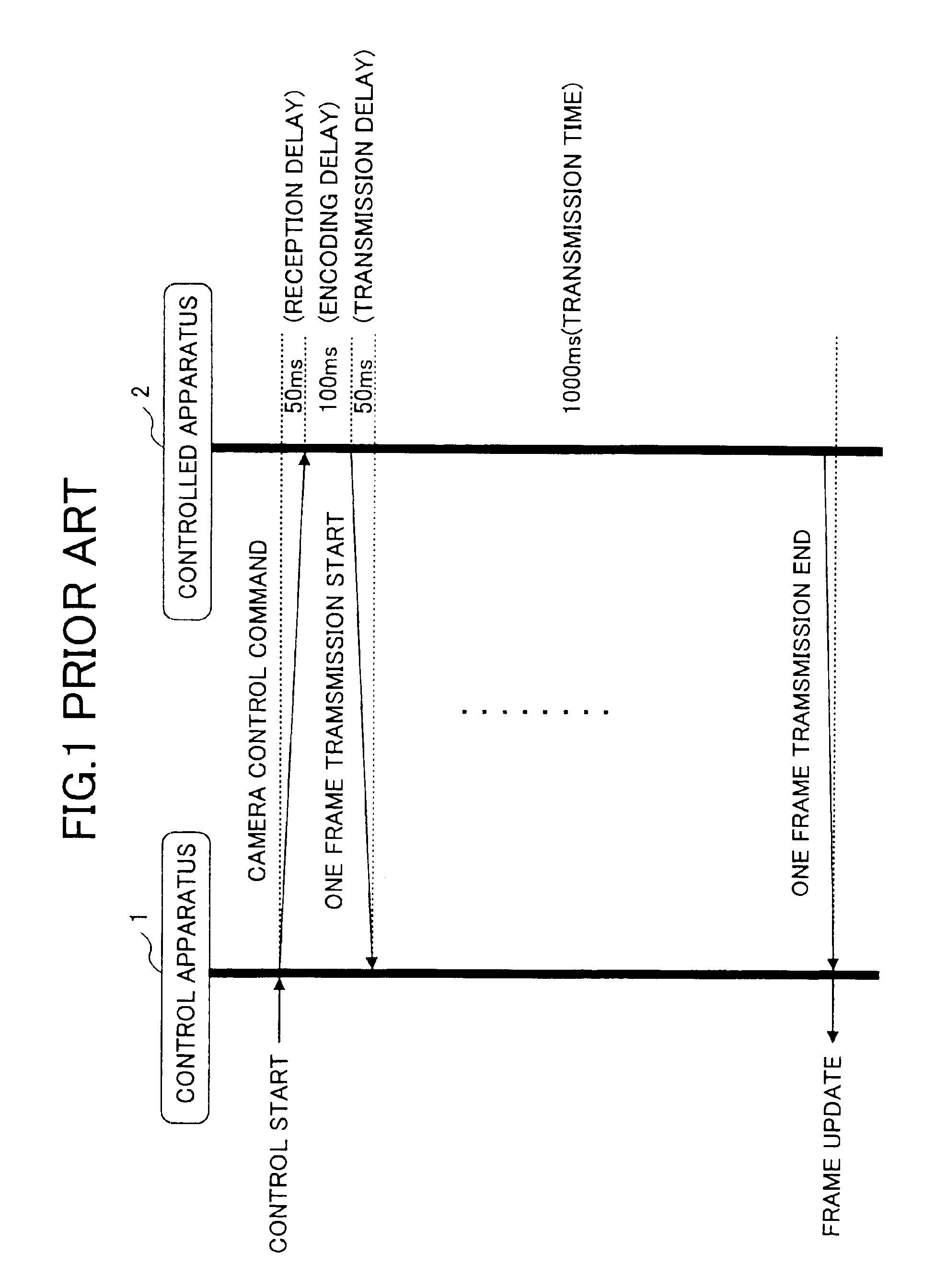
Therefore, in the low-speed network, the amount of data to be transmitted becomes large for the network bandwidth, and a delay is prone to be caused in the data transmission.
As a result, a response to the camera control is delayed, thus resulting in poor camera operability.
This, however, does not drastically improve the response, but has a disadvantage of causing deterioration in video quality.

Method used


Image

  • Image display control system reducing image transmission delay
  • Image display control system reducing image transmission delay
  • Image display control system reducing image transmission delay

Examples


first embodiment

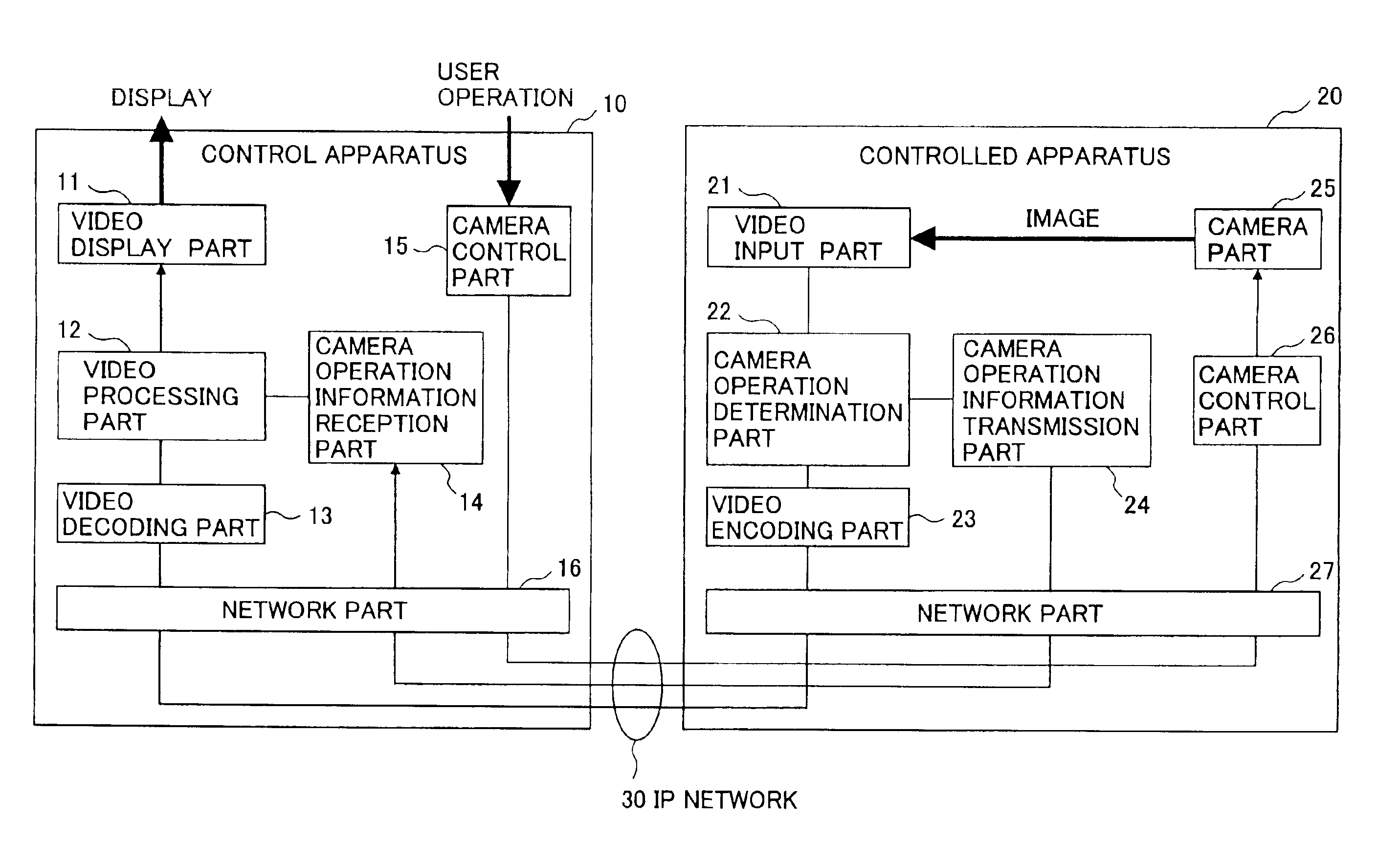
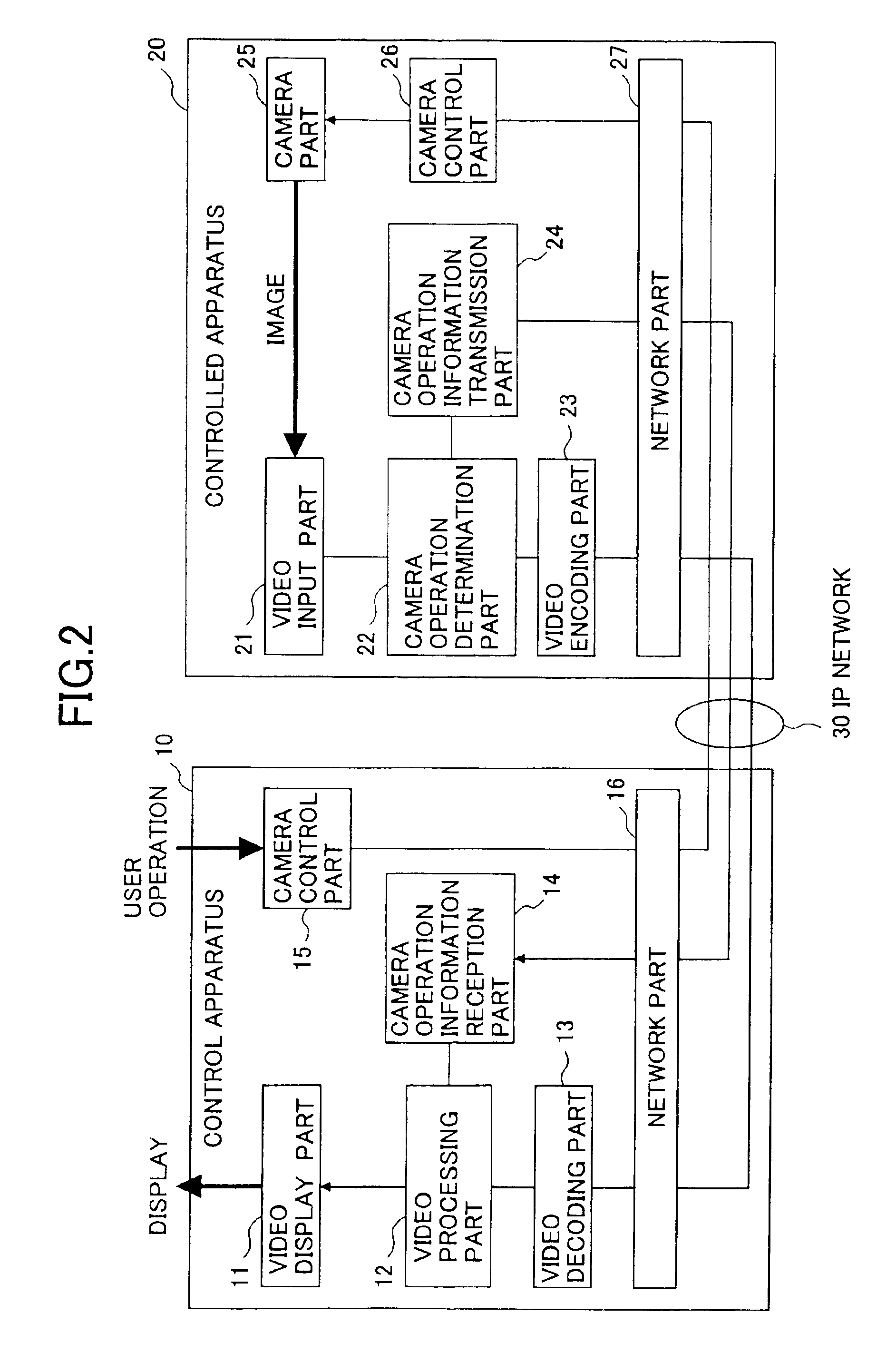
[0031]FIG. 2 shows a structure of a system to which a video display control method of the present invention is applied. In the drawing, a control apparatus 10 by which a user controls a camera and a controlled apparatus 20 including the controlled camera are connected by an IP network 30 so as to form this system structure.

[0032]The control apparatus 10 includes a video display part 11, a video processing part 12, a video decoding part 13, a camera operation information reception part 14, a camera control part 15, and a network part 16. The controlled apparatus 20 includes a video input part 21, a camera operation determination part 22, a video encoding part 23, a camera operation information transmission part 24, a camera part 25, a camera control part 26, and a network part 27.

[0033]The user inputs control information such as PAN, TILT, or ZOOM of the camera part 25 to the camera control part 15 of the control apparatus 10. The network part 16 of the control apparatus 10 and the n...

second embodiment

[0059]FIG. 10 shows a structure of the system to which the video display control method of the present invention is applied. In the drawing, the same elements as those of FIG. 2 are referred to by the same numerals, and a description thereof will be omitted. In FIG. 10, a camera control part 66 of the controlled apparatus 20 recognizes control information (camera control command) supplied from the control apparatus 10 so as to control a PAN, TILT, or ZOOM operation of the camera part 25 based on the supplied control information and activate a camera operation determination part 62 only while the camera control is performed. Thereby, the camera operation determination part 62 processes video data to determine a camera operation to be PAN, TILT, or ZOOM. Since this determination operation is performed only while the camera operation determination part 62 is activated by the camera control part 66, a wrong recognition of the camera operation can be prevented, thus increasing accuracy i...


PUM


Abstract

A video display control method comprises generating camera operation information concerning an operation of a camera operated by remote control, transmitting data of video captured by the camera and the camera operation information to a control apparatus via a network; and processing the data of the video based on the camera operation information to display an image of the video at the control apparatus.

Description

BACKGROUND OF THE INVENTION[0001]1. Field of the Invention[0002]The present invention generally relates to video display control methods, video display control systems, and apparatuses employed in such systems, and more particularly to a video display control method and a video display control system that control a camera from a remote location via a network and transmit video captured by the camera via the network to display the captured video, and an apparatus employed in such a system.[0003]2. Description of the Related Art[0004]Recently, the communication network environment has been shifting from circuit switching to an IP (internet protocol) network, which also requires video communication to be performed via the IP network. Video transmission as well as camera control is performed via a relatively low-speed IP network also in a video monitoring system that performs the camera control from a remote location. In this case, in order to perform the camera control accurately, it i...

Claims


Application Information

Patent Timeline
IPC IPC(8): H04N5/232H04N5/14
CPCH04N5/232H04N5/23203H04N5/23206H04N5/145H04N23/66H04N23/661H04N23/63H04N23/695
Inventor MIURA, MASAKIKOBAYASHI, KENZO
Owner FUJITSU LTD
Learn More