
Image reading apparatus, default value adjusting method of image reading apparatus, and chart original

Inactive Publication Date: 2005-11-01
FUJIFILM CORP
View PDF12 Cites 18 Cited by
  • Summary
  • Abstract
  • Description
  • Claims
  • Application Information

AI Technical Summary

Benefits of technology

[0007]The present invention has been devised to overcome the above problems. An object of the present invention is to provide an image reading apparatus and a default value adjusting method of an image reading apparatus which reduce the work involved in adjustment. Further, an object of the present invention is to provide a chart original which facilitates detection of positional offset between an original holding portion and an image reading element.
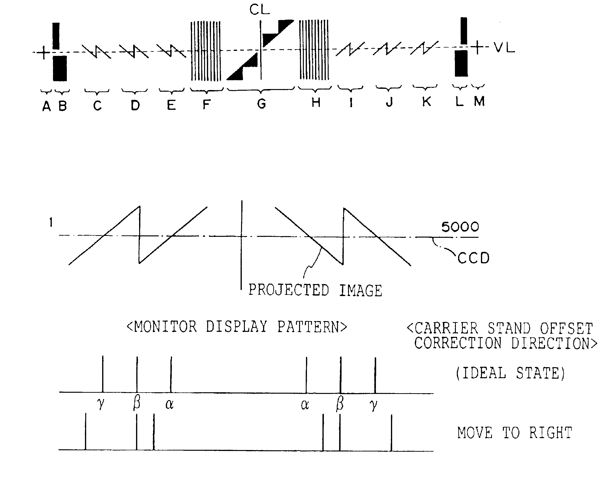
[0038]The positional offset between the original holding portion and the image reading element can be detected by using the chart original of the present invention, in which two or more patterns are disposed so as to be separated at predetermined intervals and so as to be symmetric with respect to a second imaginary line which is orthogonal to a first imaginary line, each of the patterns being formed from a first line segment, which is orthogonal to the first imaginary line, and two second line segments, which are disposed at opposite positions with respect to the first line segment so as to intersect the first line segment, and each of the patterns intersecting the first imaginary line at the three points. The chart original of the present invention is disposed such that the first imaginary line is oriented in a direction corresponding to the direction in which the plural pixels of the image reading element are arrayed. By detecting the intervals between three points intersecting the direction in which the pixels are arrayed, the positional offset between the original holding portion and the image reading element can be corrected.

Problems solved by technology

However, in the conventional adjusting method described above, although the burden on the operator in terms of time and labor is reduced after the default value is adjusted, however, during adjustment, much time is required, since the default value must be adjusted for each size of the photographic film while viewing the display screen.

Method used


Image

  • Image reading apparatus, default value adjusting method of image reading apparatus, and chart original
  • Image reading apparatus, default value adjusting method of image reading apparatus, and chart original
  • Image reading apparatus, default value adjusting method of image reading apparatus, and chart original

Examples


Embodiment Construction

[0058]Below, an explanation will be provided of an embodiment of the present invention while referring to the Figures.

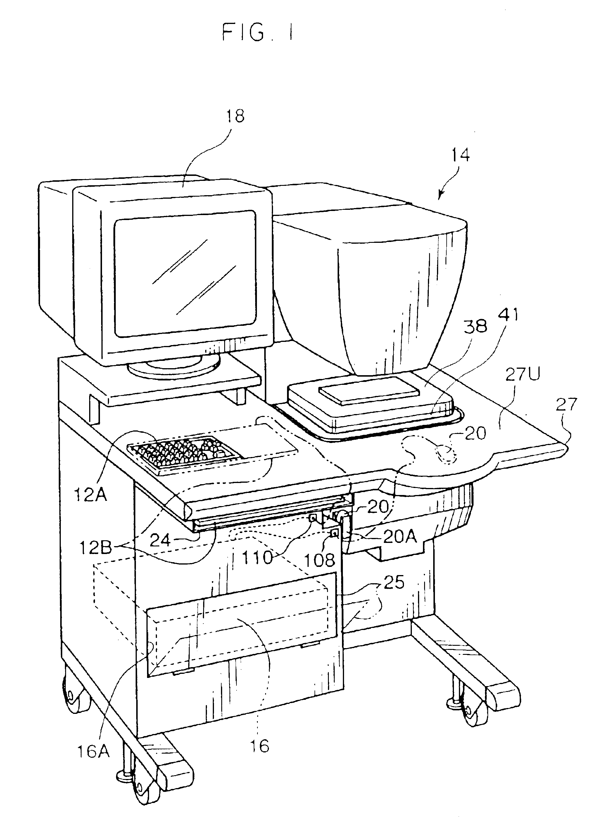
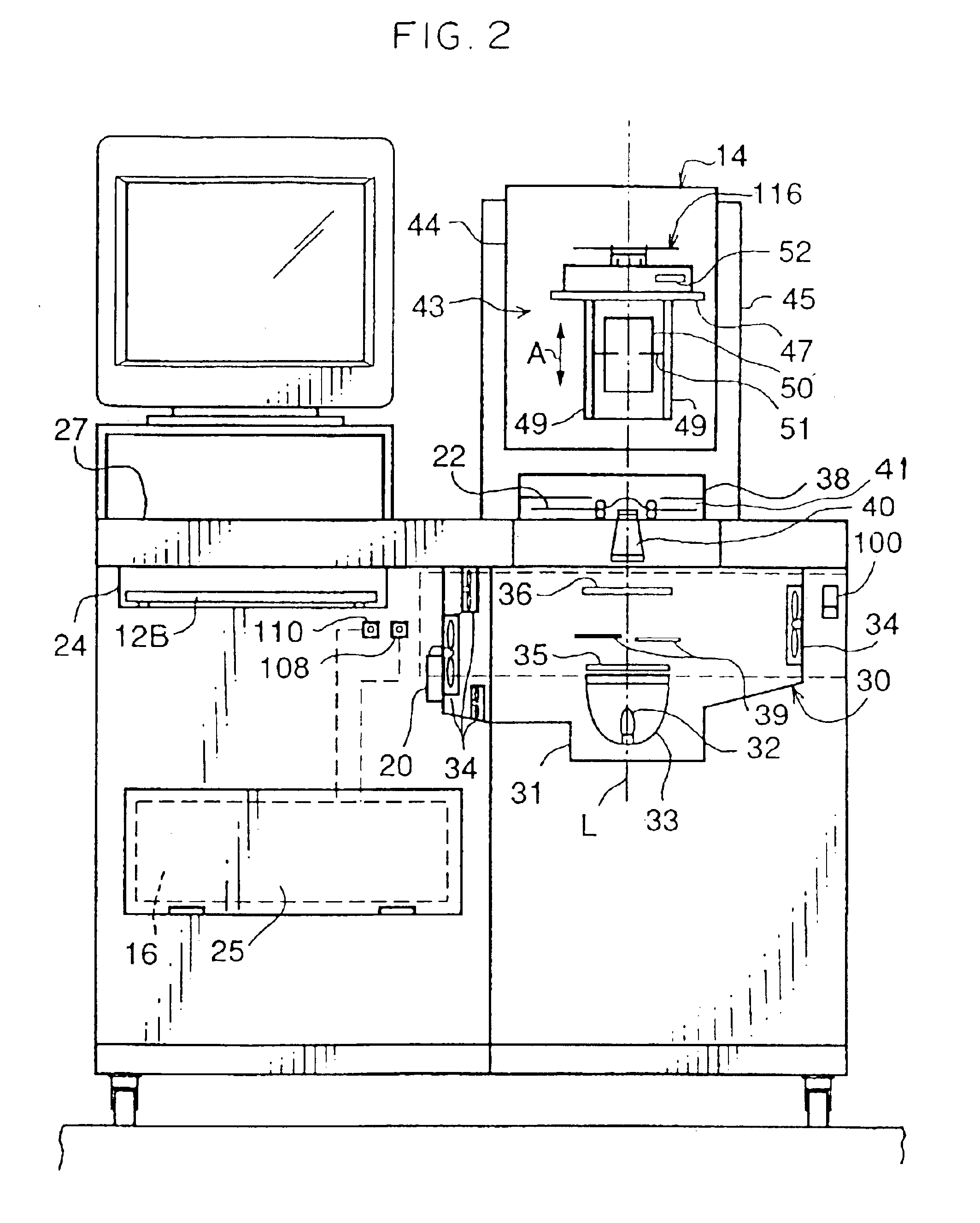
[0059]As illustrated in FIG. 1, a line CCD scanner 14 of an image reading apparatus of the present embodiment is provided with a work table 27 having disposed thereon: an image processing section 16 formed with a personal computer; a mouse 20 connected to the image processing section 16; two types of keyboards 12A, 12B connected to the image processing section 16; and a display 18 connected to the image processing section 16.

[0060]One of the keyboards, the keyboard 12A, is embedded in a work surface 27U of the work table 27. The other keyboard, the keyboard 12B, is contained within a tray 24 provided at a lower side of the work table 27. During use, the keyboard 12B is removed from the tray 24, and is placed on top of the keyboard 12A. At this time, a cord of the keyboard 12B is connected to a jack 110 connected to the image processing section 16, and used. During us...


PUM


Abstract

A chart original in which two or more patterns are disposed so as to be separated at predetermined intervals and are symmetric with respect to a second imaginary line which is orthogonal to a first imaginary line. Each of the patterns is formed from a first line segment, which is orthogonal to the first imaginary line, and two second line segments, which are disposed at opposite positions with respect to the first line segment so as to intersect the first line segment. Each of the patterns intersect the first imaginary line at three points.

Description

[0001]This is a divisional of application Ser. No. 09 / 376,348 filed Aug. 18, 1999, now U.S. Pat. No. 6,631,013; the disclosure of which is incorporated herein by reference.BACKGROUND OF THE INVENTION[0002]1. Field of the Invention[0003]The present invention relates to an image reading apparatus, a default value adjusting method of an image reading apparatus, and a chart original, and in particular, relates to an image reading apparatus having default values of a resolution of a pulse motor that moves a lens unit or the like of the image reading apparatus, a default value adjusting method of an image reading apparatus which adjusts default values, and a chart original which is directly used in an embodiment of the default value adjusting method of an image reading apparatus.[0004]2. Description of the Related Art[0005]Japanese Patent Application Laid-Open (JP-A) No. 5-281631 discloses a method for adjusting a position of a zoom ring which adjusts the magnification of a zoom lens and ...

Claims


Application Information

Patent Timeline
IPC IPC(8): H04N1/00H04N1/04
CPCH04N1/00002H04N1/00018H04N1/00031H04N1/00045H04N1/00053H04N1/00063H04N1/00087H04N1/0009H04N1/0405H04N1/0432H04N2201/0408H04N2201/0416
Inventor SAKAGUCHI, YASUNOBU
Owner FUJIFILM CORP
Learn More