Time error compensating apparatus and method in a terminal

a terminal and time error technology, applied in the direction of generating/distributing signals, instruments, horology, etc., can solve the problems of increasing timing errors, affecting the accuracy of time information obtained by the user, and affecting the accuracy of time information obtained by the gsm or other terminals, so as to achieve accurate compensation for time errors

Inactive Publication Date: 2005-11-01
LG ELECTRONICS INC
View PDF12 Cites 14 Cited by
  • Summary
  • Abstract
  • Description
  • Claims
  • Application Information

AI Technical Summary

Benefits of technology

[0016]Another object of the present invention is to provide a time error compensating system and method which accurately compensates for time errors in a signal processing system which, for example, may include a GSM or other communications terminal.
[0017]Another object of the present invention is to provide a time error compensating system and method of the aforementioned type which compensates for time errors which specifically arise as a result of external conditions such as temperature and / or voltage changes.

Problems solved by technology

Although the crystal oscillator can maintain a precise dock timing within a narrow temperature range, frequency variation becomes great and timing error is increased if the crystal is exposed to temperatures outside of a predetermined range.
There are many problems with time generation in the related art.
This makes it impossible for the user to obtain accurate time information from the GSM or other terminal.
However, such a crystal is relatively expensive compared to the more rudimentary low-priced crystal.
Moreover, it is difficult to obtain an accuracy of better than 3˜5 ppm (0.26˜0.43 sec / day) even with a more stable crystal.

Method used


Image

  • Time error compensating apparatus and method in a terminal
  • Time error compensating apparatus and method in a terminal
  • Time error compensating apparatus and method in a terminal

Examples


Embodiment Construction

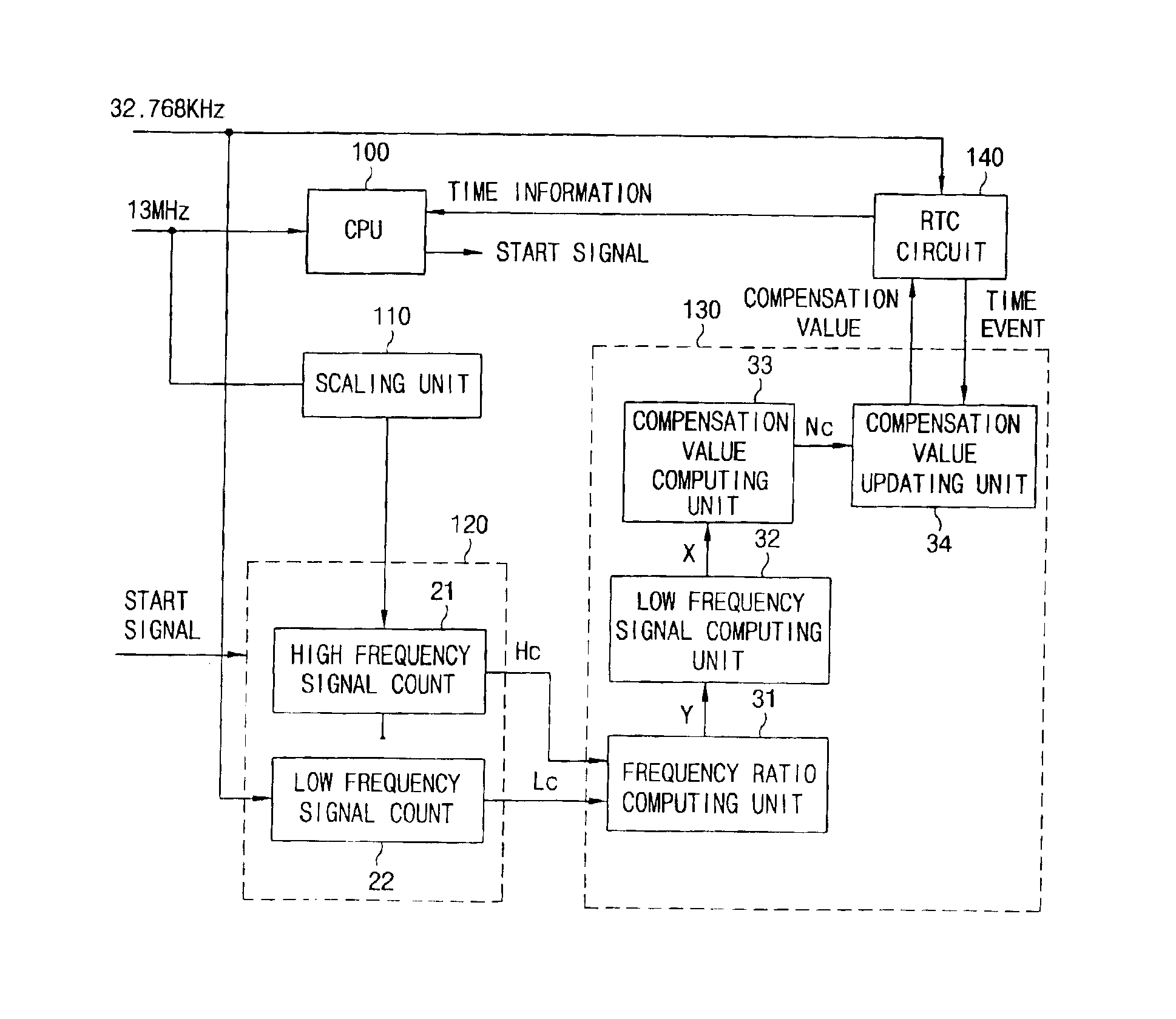
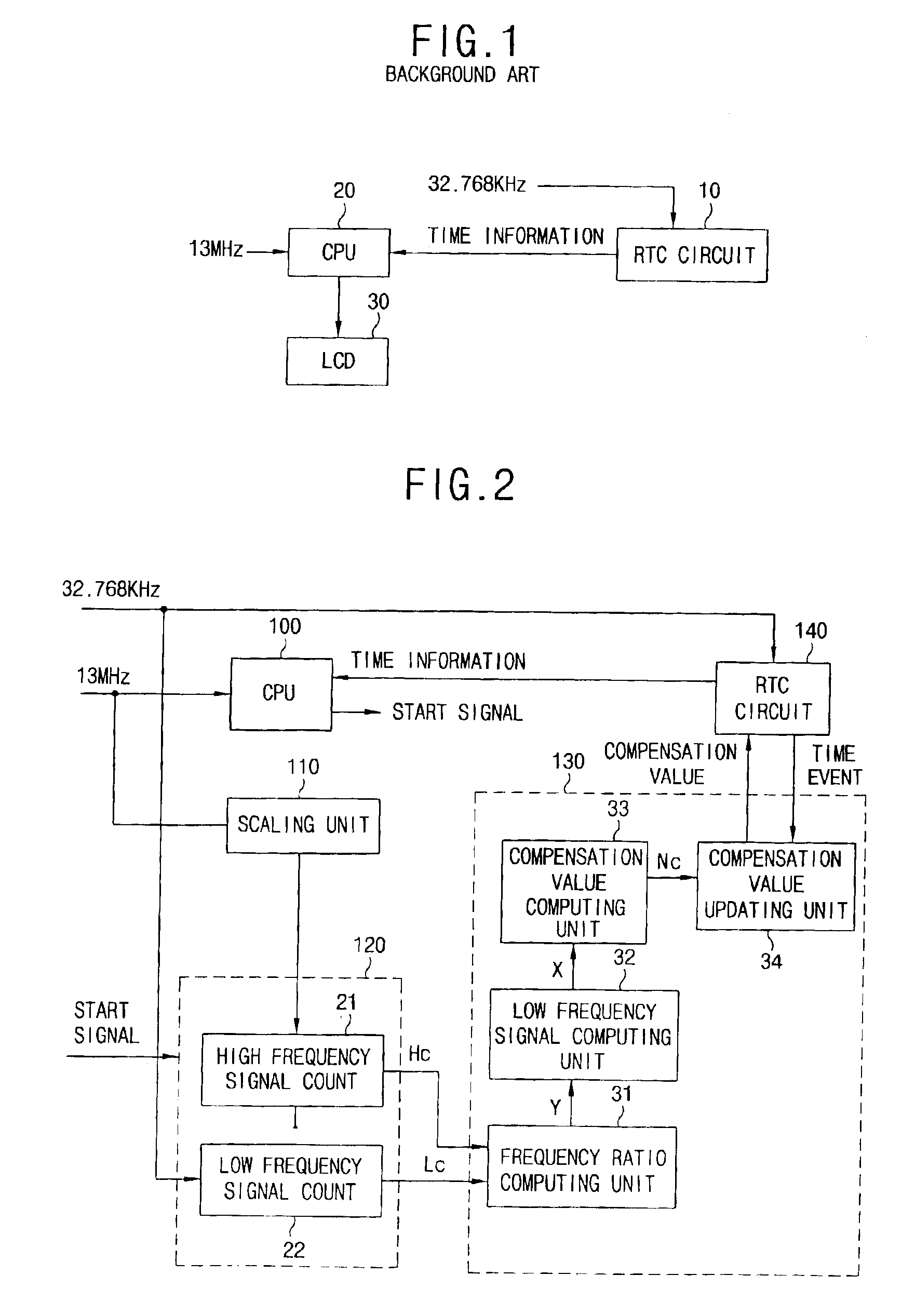
[0028]A GSM or other terminal may include a system clock which generates, for example, a 10 MHz or a 13 MHz high-frequency clock signal for driving a main chip set (Chipset) of the terminal. This high-frequency clock signal may be generated from a voltage-controlled, temperature-compensated crystal oscillator (VCTCXO), which has been shown to demonstrate improved resistance to changes in temperature and which has an accuracy of below 0.15 ppm. In accordance with the present invention, a compensation count value of a low-frequency clock signal is computed using this accurate high-frequency clock signal, and the computed compensation count value is then used as a basis for correcting time errors in, for example, a real-time clock of the terminal.

[0029]FIG. 2 shows a time error compensating apparatus which, for example, may be used in a GSM or other communications terminal in accordance with one embodiment of the present invention. This apparatus includes a CPU 100, a scaling unit 110,...


PUM


Abstract

A time-error-compensating apparatus and method corrects errors in a real-time clock caused by temperature fluctuations or other external influences. The apparatus includes a frequency counting unit which counts a high-frequency clock signal and a low-frequency clock signal, and a time compensating unit which computes a clock count compensation value based on a comparison of the count values of of the low-frequency and high-frequency clock signals. Correcting time using a high-frequency clock is highly desirable because a clock of this type has proven to be accurate in high external stress conditions. Use of this clock also allows the real-time clock to be implemented as a low-frequency, inexpensive low-frequency clock. The method and apparatus are well suited to correcting time information in the terminals of a mobile communications system, or in any other system or device where time tracking is sought.

Description

BACKGROUND OF THE INVENTION[0001]1. Field of the Invention[0002]The present invention relates to generating time in a signal processing system, and more particularly to a system and method for performing time correction in, for example, a communications system.[0003]2. Background of the Related Art[0004]A Global System Mobile (GSM) terminal and other remote terminals display time using a self-contained RTC circuit, rather than using time information transmitted from a base station.[0005]As shown in FIG. 1, conventional GSM terminals includes a real-time clock (RTC) circuit 10 for counting a low-frequency clock signal of 32.768 KHz and generating time information (second, minute and hour), and a CPU 20 for displaying the time information on LCD 30 generated in synchronization with a high-frequency clock signal of 13 MHz. In the related art, the low-frequency clock signal is generated by a crystal oscillator, and a high-frequency clock signal is a system clock signal generated by a vo...

Claims


Application Information

Patent Timeline
Patent Type & Authority Patents(United States)
IPC IPC(8): G04G3/00G04G3/02G06F1/14H04B7/26H04B1/40
CPCG04G3/00G04G3/027G06F1/14H04B7/2678H04B1/40
Inventor JUNG, DONG SOO
Owner LG ELECTRONICS INC
Why Eureka
Try Eureka