Charging device using a charge roller and image forming apparatus including the same

a charging device and charge roller technology, applied in the direction of electrographic process apparatus, instruments, corona discharge, etc., can solve the problems of film peeling at seams in circumferential direction, increasing attention for the contact type of charging device, and reducing the life of the charging devi

Inactive Publication Date: 2005-11-01
RICOH KK
View PDF14 Cites 18 Cited by
  • Summary
  • Abstract
  • Description
  • Claims
  • Application Information

AI Technical Summary

Benefits of technology

[0011]It is an object of the present invention to provide a discharging device capable of forming an accurate gap between a charge roller or charging member and an image carrier and an image forming apparatus including the same.
[0012]It is another object of the present invention to provide a charging device capable of protecting gap forming members from deterioration while enhancing durability thereof and an image forming apparatus including the same.
[0013]It is still another object of the present invention to provide a charging device capable of preventing gap forming members from getting on steps formed in opposite end portions of a charge roller and obviating discharge in the opposite end portions outside of the image forming members and an image forming apparatus including the same.
[0014]It is yet another object of the present invention to provide a charging device capable of preventing smears from accumulating on a charge roller without regard to the thickness deviation pattern of gap forming members and an image forming apparatus including the same.
[0015]It is a further object of the present invention to provide a low cost, highly durable charging device and an image forming apparatus including the same.

Problems solved by technology

While a scorotron charger, corotron charger or similar non-contact type of charging device that does not contact the image carrier has been commonly used, a contact type of charging device is attracting increasing attention because the non-contact type of charging device produces a large amount of undesirable discharge products including ozone.
However, a charging device using a charge roller has a problem that toner and impurities accumulate on the surface of the charge roller little by little and make charging irregular, thereby reducing the life of the charging device.
The films, however, start peeling at seams in the circumferential direction of the charge roller due to repeated contact of the charge roller and image carrier.
Further, the drum and charge roller are more likely to contact each other if they are eccentric or nor parallel to each other.
Although the charge roller may be machined after the tubes have been fitted thereon, such a procedure is not only time-consuming but also liable to cause the tubes to turn during machining, resulting an increase in cost.
Another problem with the tube scheme is that when the tubes, which are thermally shrinkable and simply fitted in the annular grooves of the charge roller, lose elasticity due to aging, the edges of the tubes get on the circumferential surface of the charge roller and are damaged or increase the gap to thereby bring about abnormal discharge.
This causes the image carrier to locally wear little by little and thereby causes a charge bias to leak.
In addition, it is likely that toner deposits on the charge roller due to defective cleaning and increases the gap to thereby bring about abnormal discharge.
However, this configuration is not directed toward the prevention of discharge in the portions outside of the image forming range, but directed toward easy fitting of the above members that are several millimeters thick and elastic.

Method used


Image

  • Charging device using a charge roller and image forming apparatus including the same
  • Charging device using a charge roller and image forming apparatus including the same
  • Charging device using a charge roller and image forming apparatus including the same

Examples


first embodiment

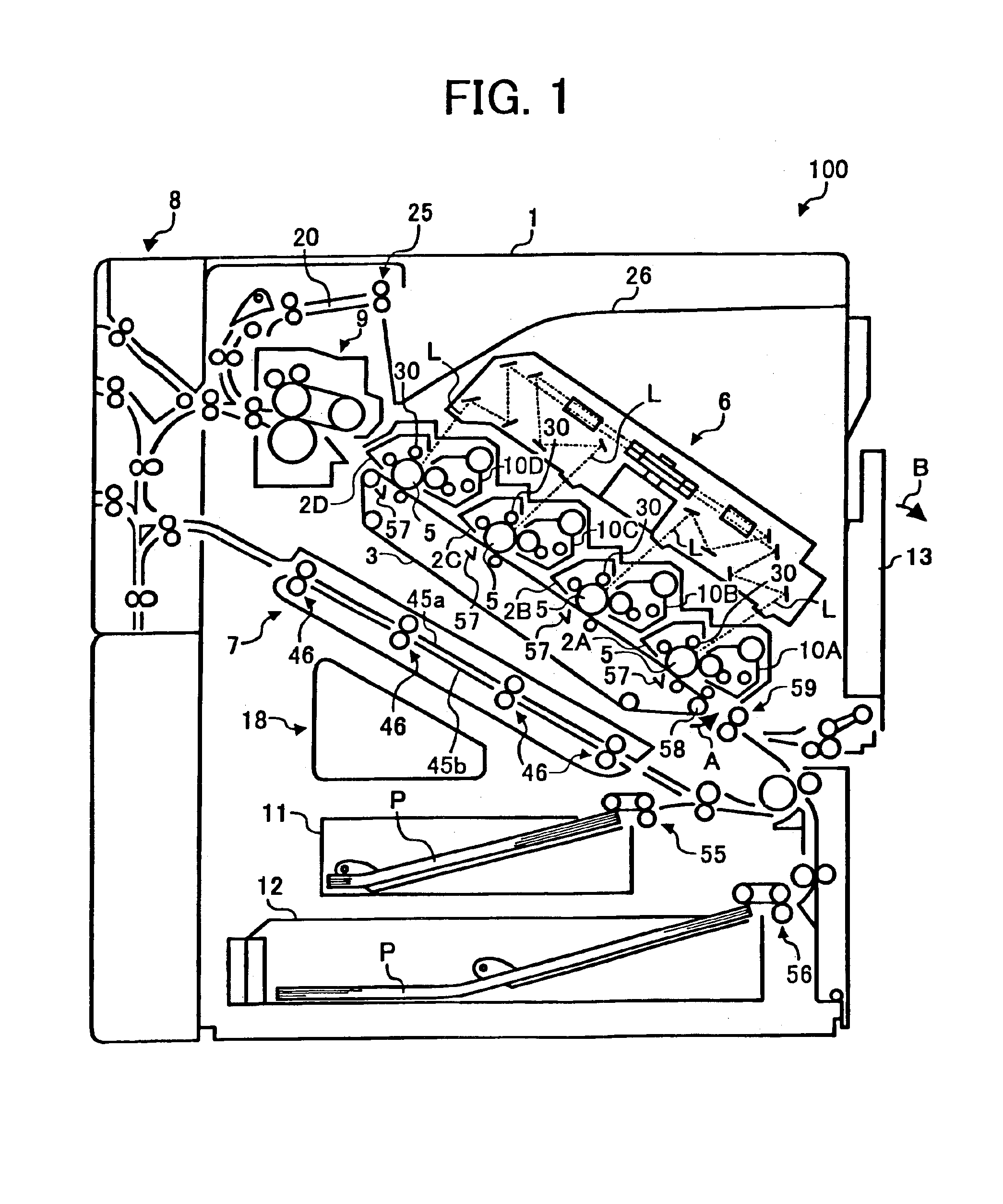
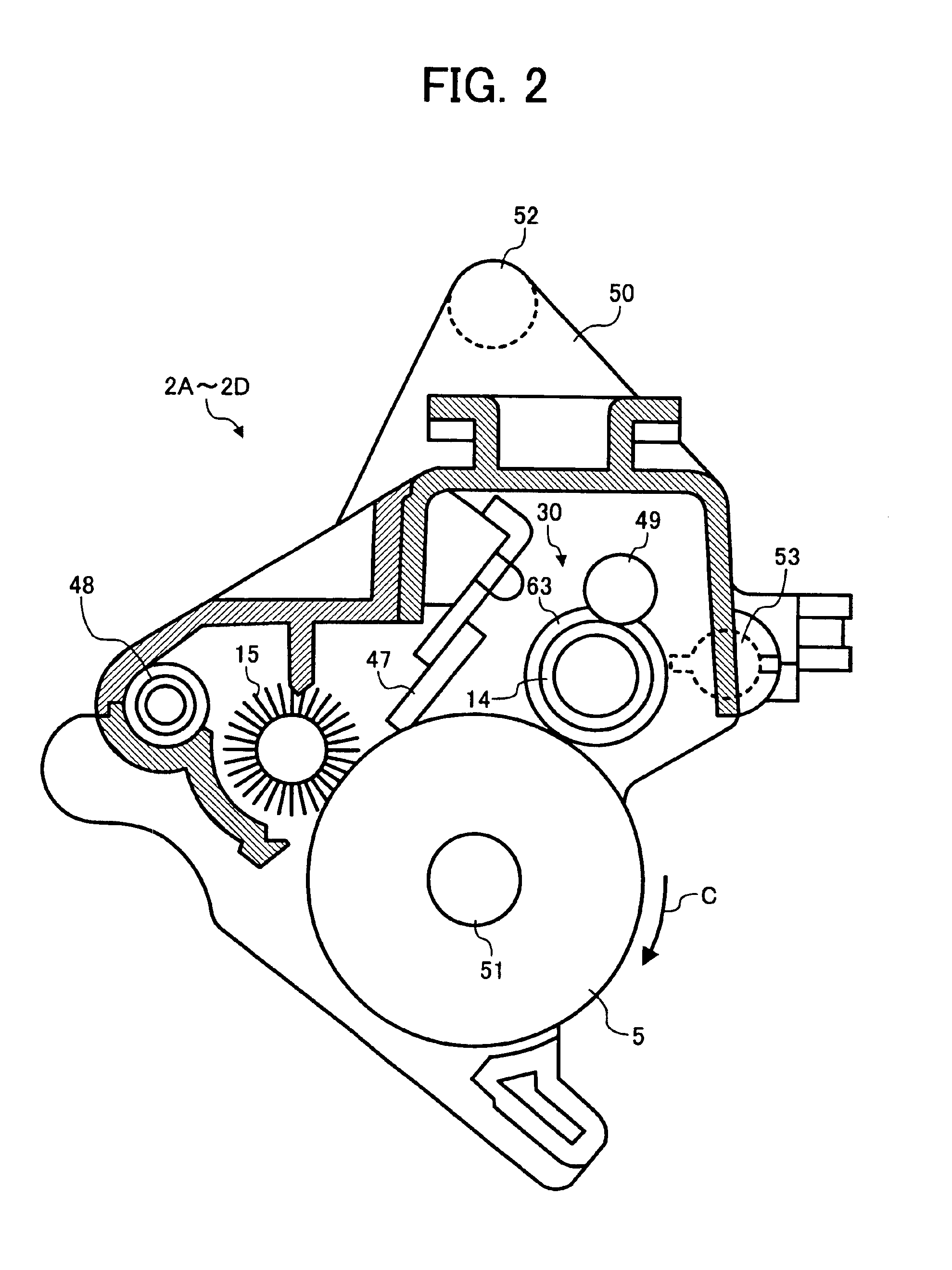
[0047]Referring to FIG. 1 of the drawings, an image forming apparatus embodying the present invention is shown and implemented as a tandem full-color printer by way of example. The full-color printer may, of course, be replaced with a monochromatic printer or any one of a copier, a facsimile apparatus and other conventional image forming apparatus. As shown, the printer, generally 100, includes a printer body 1 accommodating four removable drum units or image carrier units 2A, 2B, 2C and 2D. An image transferring unit is located at substantially the center of the printer body 1 and includes an image transfer belt 3 passed over a plurality of rollers including an adhesion roller 58. The image transfer belt (simply belt hereinafter) 3 is movable in a direction indicated by an arrow A in FIG. 1. Four image transfer brushes 57 are disposed in the loop of the belt 3 and respectively face four drums 5, which are accommodated in the drum units 2A through 2D.

[0048]In the illustrative embodi...

example 1

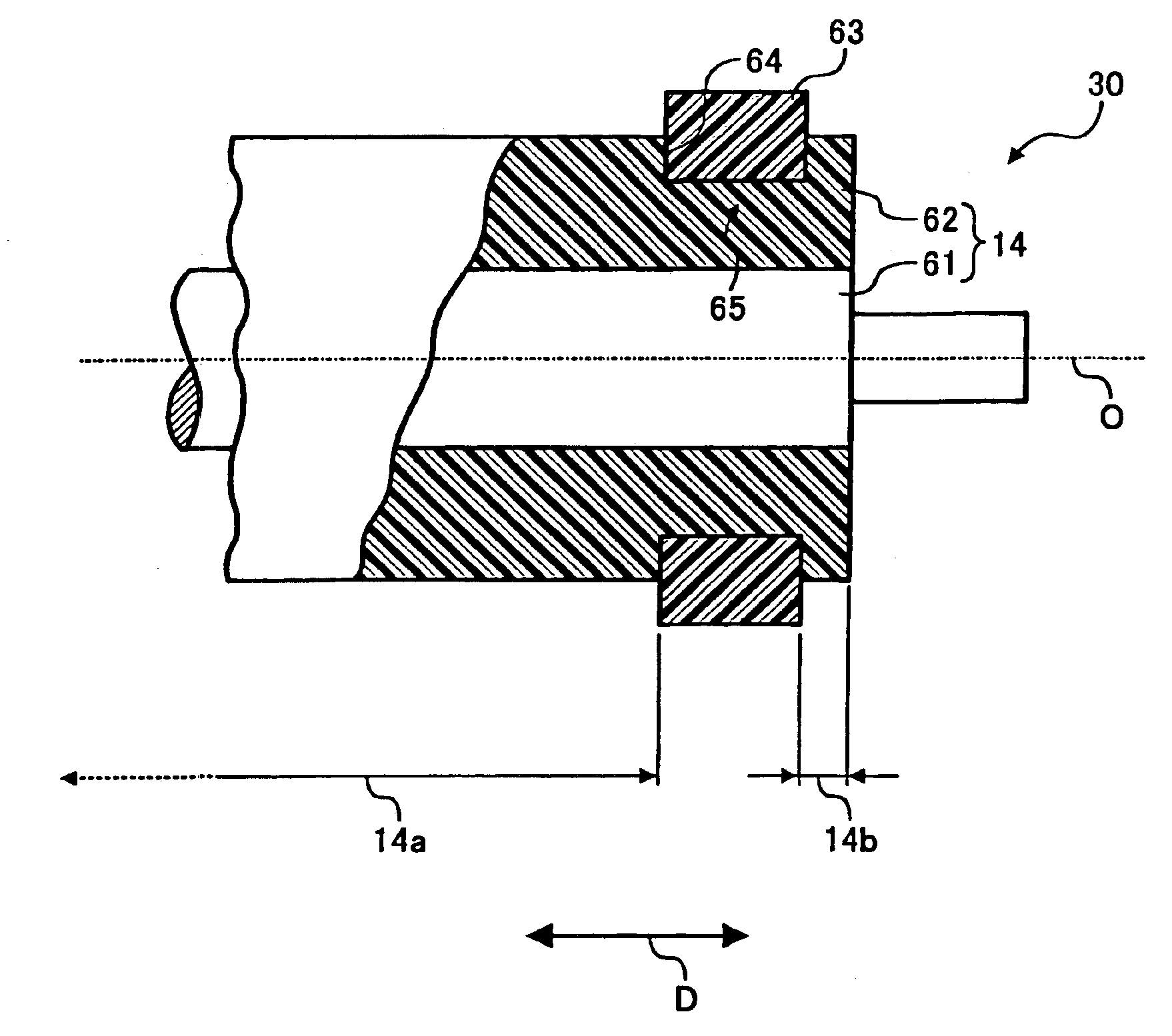
[0101]The charge roller 14 was produced by the following procedure. The core 61 was formed of stainless steel and provided with a diameter of 8 mm. To form the resin layer 62, 60 pts.wt. of ion-conductive agent was added to 100 pts.wt. of ABS resin to prepare a resin component having volumetric resistivity of 106 Ω·cm. Injection molding was effected with the above resin component to form the resin layer 62 on the core 61. Subsequently, the surface of the resin layer 62 was machined to provide the charge roller 14 with a diameter of 12 mm. At this instant, the stepped portions 64 were formed in opposite end portions of the resin layer 62 to thereby form the annular grooves 65 having width of 8 mm each. Subsequently, a 150 μm thick PFA tube was cut to produce two 8 mm wide, gap forming members 63. The two gap forming members 63 each were fitted in one of the annular grooves 65 and caused to shrink by being heated for 20 minutes in a 120° C. atmosphere. When the charge roller 14 thus p...

second embodiment

[0119]A second embodiment of the image forming apparatus will be described with reference to FIG. 5 hereinafter. This embodiment is substantially identical with the first embodiment shown in FIGS. 1 and 2 as to the construction and operation. The following description will concentrate on differences between the first and second embodiments.

[0120]FIG. 5 shows in a section the charge roller 14 and gap forming member 63 included in the illustrative embodiment. As shown, the gap forming member 63, stepped portion 64 and annular groove 65 differ in configuration from the corresponding constituents shown in FIG. 3. As for the rest of the configuration, the illustrative embodiment is identical with the first embodiment. Of course, reference numerals shown in FIG. 5 correspond to the reference numerals shown in FIG. 3.

[0121]When the gap forming member 63 is implemented as thermally shrinkable tube that must be highly durable, durability can be insured if the tube is sufficiently thick, as s...


PUM


Abstract

An image forming apparatus of the present invention includes a charging device including a charge roller formed with annular grooves at opposite end portions thereof and configured to charge an image carrier. Annular gap forming members each are fitted in the annular grooves for forming a gap between the charge roller and the image carrier. The gap forming members each have an area of 1.0×10⁻⁶ m2 to 3.0×10⁻⁶ m2 in a section containing the axis of the charge roller.

Description

BACKGROUND OF THE INVENTION[0001]1. Field of the Invention[0002]The present invention relates to a charging device for charging a photoconductive drum or similar image carrier with a charge roller and a copier, facsimile apparatus, printer or similar image forming apparatus including the same.[0003]2. Description of the Background Art[0004]Generally, an image forming apparatus includes a charging device for charging a photoconductive drum or similar image carrier during an image forming process. While a scorotron charger, corotron charger or similar non-contact type of charging device that does not contact the image carrier has been commonly used, a contact type of charging device is attracting increasing attention because the non-contact type of charging device produces a large amount of undesirable discharge products including ozone. Among some different contact type of charging devices available today, a charging device having a charge roller pressed against the image carrier is ...

Claims


Application Information

Patent Timeline
Patent Type & Authority Patents(United States)
IPC IPC(8): G03G15/02
CPCG03G15/025G03G2215/02
Inventor KOSUGE, AKIO
Owner RICOH KK
Why Eureka
Try Eureka