
System and method of measuring convection induced impedance gradients to determine liquid flow rates

a technology of impedance gradient and convection, applied in the field of liquid flow rate measurement, can solve the problems of inability to account for dynamic variations in fluid flow, inability to achieve continuous flow measurement, etc., to achieve high reproducibility results, reduce the cycle time of gradient, and not increase the dead volume within the flow channel

Inactive Publication Date: 2005-11-08
WATERS TECH CORP
View PDF4 Cites 1 Cited by
  • Summary
  • Abstract
  • Description
  • Claims
  • Application Information

AI Technical Summary

Benefits of technology

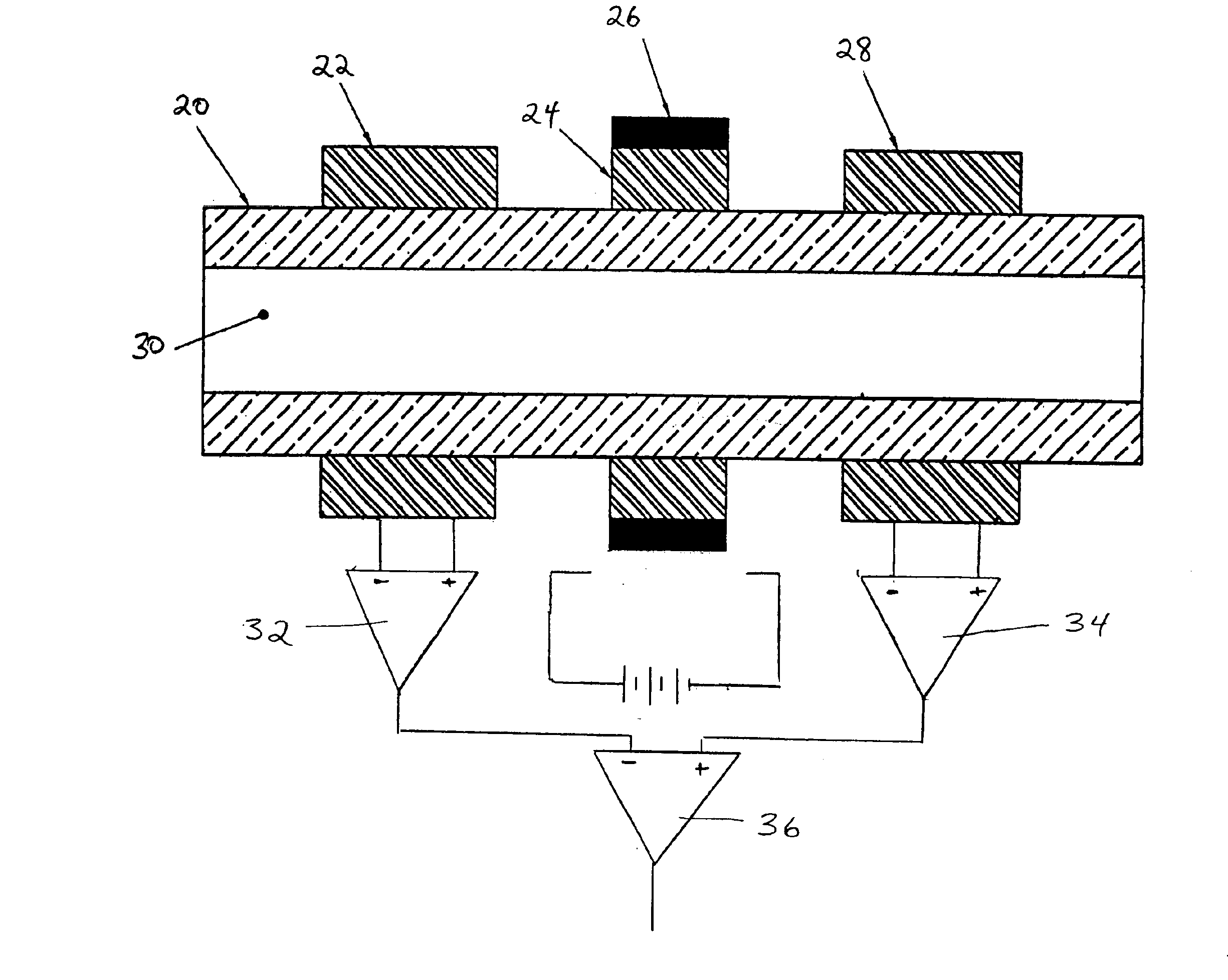
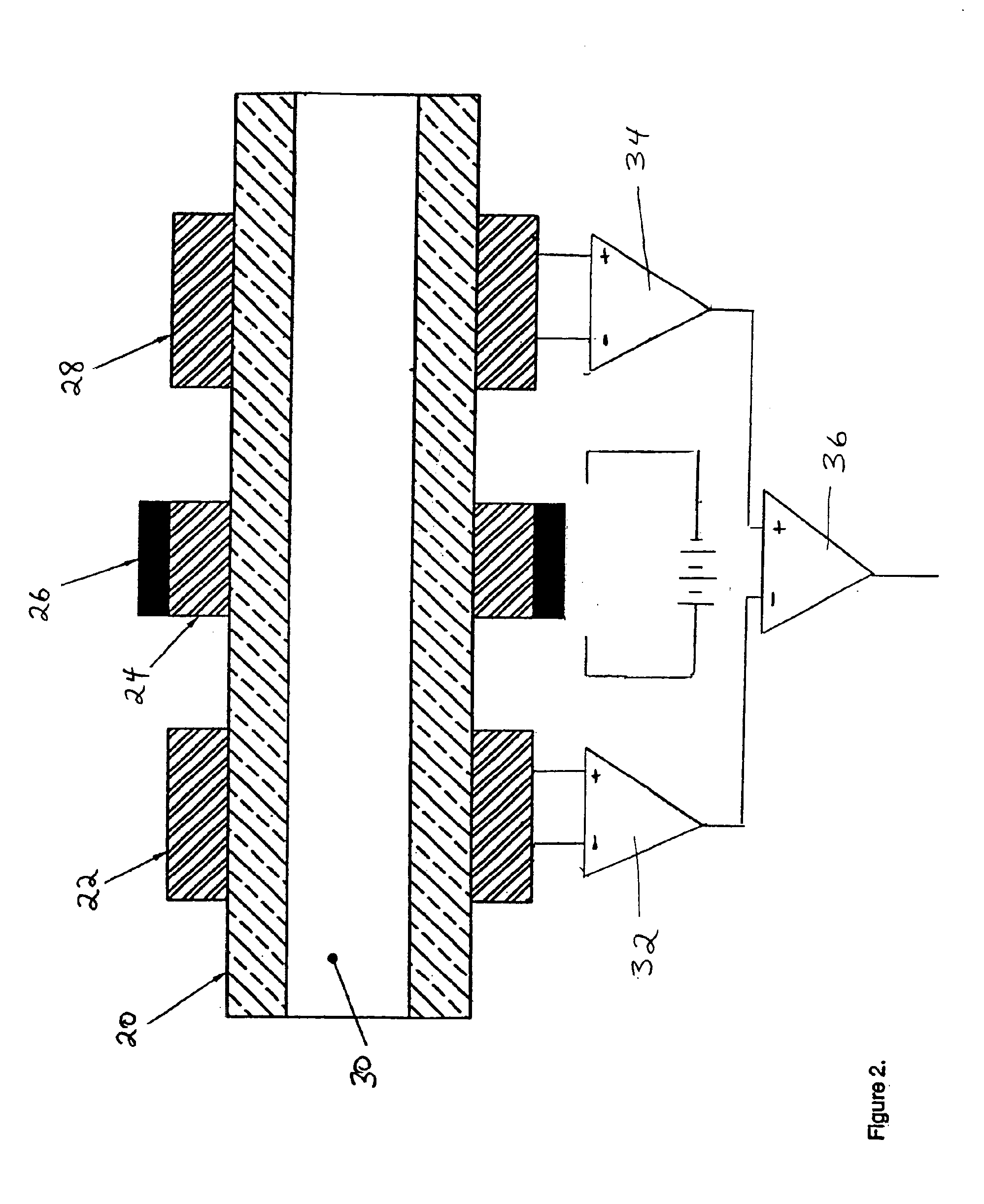
[0009]The present invention allows the user to measure fluid flow rate while simultaneously minimizing dead volume in a chromatographic environment wherein small fluid flows are present. The minimizing of dead volume reduces the cycle time of gradients, guards against convective and eddy current mixing, and aids in providing highly reproducible results. In attaining the foregoing and other objects, the present invention provides methods and apparatus for mounting an excitation source, as well as a plurality of sensor elements, to the external surface of a flow channel. The excitation source is located either in direct contact or in close proximity to the external surface of an existing flow channel. The excitation source is designed such that it may be mounted to a prexisting flow channel, thereby allowing retrofitting of existing systems. The excitation source may take the form of an alternating current (AC) generator coupled with an integral heating means. Additionally, alternate forms of excitations sources may be substituted as understood by those skilled in the art.
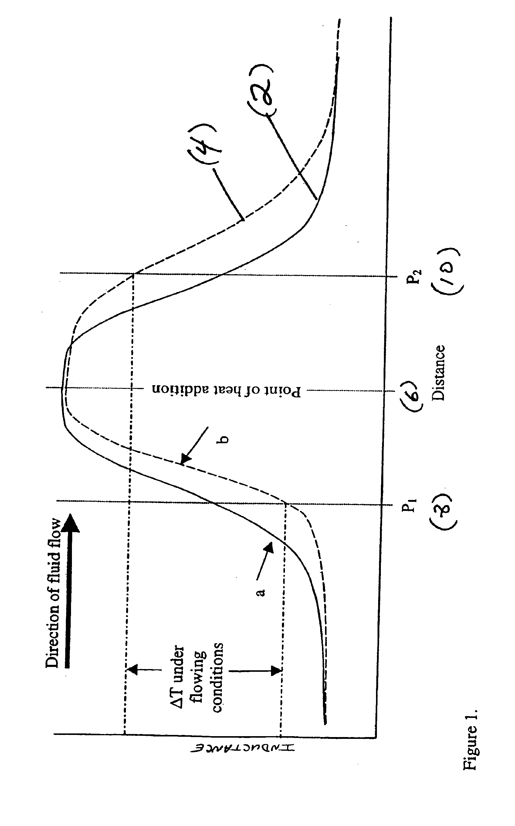
[0010]In addition to the excitation source, a plurality of sensor elements are located in positions upstream and downstream of the excitation source. Similar to the excitation source, these sensor elements are designed such that they may be installed on a prexisting flow channel without intrusive modifications. In light of this, dead volume within a flow channel is not increased by adding unnecessary couplings, fittings or other forms of extraneous paraphernalia associated with the installation of a direct contact sensor element. This excitation source comprises a heating element, used in elevating the temperature of the fluid, as well as an alternating current (AC) signal generator. This heater and AC generator are packaged together, and are located around the external surface of a flow channel. Following the addition of heat to the fluid, the fluid impedance will change. This change in impedance may be detected by a plurality of sensor means located in positions both upstream and downstream of the excitation source location. A preliminary impedance reading at upstream and downstream sensor locations under a zero flow condition may be recorded thereby providing a baseline representation of impedance conditions within the flow channel. Such a baseline representation will result in a symmetrical impedance gradient centered at the point of excitation. Furthermore, additional impedance readings from the aforementioned plurality of sensor means may be recorded under fluid flow conditions, thereby yielding a asymmetrical impedance gradient around the central excitation element. These aforementioned sensor means are in electrical communication with a calculation means, wherein said calculation means comprises a high gain differential amplifier capable of receiving electrical information from said sensors. This high gain differential amplifier yields an electrical voltage proportional to the fluid flow rate within the flow channel. Under a zero flow condition, for example, this calculation means will yield a zero output voltage. Under a flowing fluid scenario, for example, the output of this high gain differencing amplifier may be represented by a positive voltage proportional to the fluid velocity within the channel. The flow rate measurement may be continuous in nature and provides instantaneous values of flow rate within a flow channel. In light of such an arrangement, continuous flow measurement may be calculated which represent actual flow conditions within a channel at any instant in time. When coupled to a High Pressure Liquid Chromatographic system (HPLC), the present invention may be utilized in providing flow feedback information to the HPLC system operating in a sub 50 μL / min environment, to thereby verify delivery performance of the pumping means.

Problems solved by technology

Such sampling, therefore, results in finite flow measurements, incapable of accounting for dynamic variations in fluid flow during those periods outside of the time of flight measurement period.
While the localized heating and temperature measurement of a fluid, as set forth above, is useful in a variety of industrial applications, the overall flow measurement accuracy is limited by several system inherent sources of error.
Such an increase in accuracy requires the use of a significantly more expensive thermocouple device.
Furthermore, under a temperature based system, there exist additional sources of system error which are not easily prevented.
One such source of error lies in the thermal conduction of heat through the walls of the fluid channel.
Such conductive heat transfer from heat source to thermocouple position results in the loss of flow measurement accuracy, as the thermocouple is no longer solely recording fluid temperature, but rather is under the influence of additional heat addition through the walls of the flow channel.
Convective losses of heat along the flow channel exterior additionally contribute to the inherent system inaccuracies.
Numerous attempts have been made in the art to prevent these conductive and convective losses, all of which result in increases in system cost and complexity.
Direct contact between an internal temperature probe and fluid, however, results in potential contamination of the fluid or of the temperature probe element.
As the fluid is in direct contact with the internal probe, particulate matter suspended in a flowing fluid may contaminate the external temperature sensing region of a temperature probe, thereby resulting in inaccurate measurements.
Furthermore, in the presence of highly corrosive or chemically reactive fluids, contact between the internal temperature probe and these fluids may result in the break down of the internal temperature probe surface, thereby resulting in the introduction of contaminant into the flowing fluid.
These extraneous additions introduce numerous sources of failure or leakage.
Such fittings introduce several potential failure locales when compared to a continuous, uninterrupted flow channel.
Additionally, the introduction of these aforementioned temperature sensors into the fluid channel greatly increases system costs and complexity.
This fluid may be either stagnant or dynamic in nature and may unpredictable escape into the fluid channel thereby causing the shape of the fluid pulse to be altered from the desired shape.

Method used


Image

  • System and method of measuring convection induced impedance gradients to determine liquid flow rates
  • System and method of measuring convection induced impedance gradients to determine liquid flow rates
  • System and method of measuring convection induced impedance gradients to determine liquid flow rates

Examples


Embodiment Construction

[0013]FIGS. 1 and 2, wherein like parts are designated by like reference numerals throughout, illustrate an example embodiment of a system and method suitable for measuring the flow of a liquid through a flow channel. This system and method may be used alone or in combination with a High Pressure Liquid Chromatography device. Although the present invention is described with reference to the example embodiments illustrated in the figures, it should be understood that many alternative forms could embody the present invention. One of ordinary skill in the art will additionally appreciate different ways to alter the parameters of the embodiments disclosed, such as the heating means, size, or type of sensor means, in a manner still in keeping with the spirit and scope of the present invention.

[0014]Referring to FIG. 1, a static impedance distribution (2) is shown wherein thermal energy and an alternating current signal is introduced at a fixed excitation point (6), and fluid impedance is...


PUM

PropertyMeasurementUnit
flow rateaaaaaaaaaa
liquid flow ratesaaaaaaaaaa
flow rateaaaaaaaaaa

Abstract

A method and system for measuring the flow rate of a liquid or gas within a flow channel utilizing a centrally located excitation source and a plurality of sensor means. Said excitation means is comprised of a heating element coupled with an alternating current generator. Of the plurality of sensor means, at least one of said sensors is located in a position upstream of the excitation source location, and additionally a second of said plurality of sensors is located in a position downstream of the excitation source. Instantaneous fluid flow rate is calculated utilizing a high gain differential amplifier electrically coupled to said sensors, wherein the convectively induced inductive gradient of the flowing fluid is compared to the symmetrical zero flow induction gradient. Following such a comparison, a voltage signal proportional to the flow of fluid within the channel is derived.

Description

TECHNICAL FIELD[0001]The present invention relates generally to the measurement of liquid flow rates through a defined tube or channel, and specifically relates to the continuous flow measurement of flows less than 50 μL / min.BACKGROUND OF THE INVENTION[0002]There exist many examples of flow measurement through a fixed channel or tube. The simplest of these techniques utilizes a time of flight measurement, thereby only measuring flow through a channel for a fixed time period. Such sampling, therefore, results in finite flow measurements, incapable of accounting for dynamic variations in fluid flow during those periods outside of the time of flight measurement period.[0003]More advanced techniques utilize an external excitation and measurement means. In exciting a fluid, a heating means is typically utilized, wherein such a heater is capable of delivering thermal energy to a closed fluid passageway. Two or more thermocouple probes, located upstream and downstream of the heating source...

Claims


Application Information

Patent Timeline
Patent Type & Authority Patents(United States)
IPC IPC(8): G01F1/684G01N30/32G01N30/64
CPCG01F1/6847G01N30/64G01N2030/324
Inventor GERHARDT, GEOFF C.FADGEN, KEITH
Owner WATERS TECH CORP
Learn More