Sliding door system with optical detector for safe door opening and closing

a door system and optical detector technology, applied in the direction of door/window fittings, wing operation mechanisms, constructions, etc., can solve the problems of false detection of members, inability to prevent any members from being drawn into the gap, and inability to install

Active Publication Date: 2005-11-08
MITSUBISHI ELECTRIC CORP
View PDF21 Cites 41 Cited by
  • Summary
  • Abstract
  • Description
  • Claims
  • Application Information

AI Technical Summary

Problems solved by technology

The safety installations, however, have respective drawbacks.
For example, according to the former safety installation, dust or foreign matters are retained at the bottom of the vertical recess, which results in a fals

Method used


Image

  • Sliding door system with optical detector for safe door opening and closing
  • Sliding door system with optical detector for safe door opening and closing
  • Sliding door system with optical detector for safe door opening and closing

Examples


embodiment 1

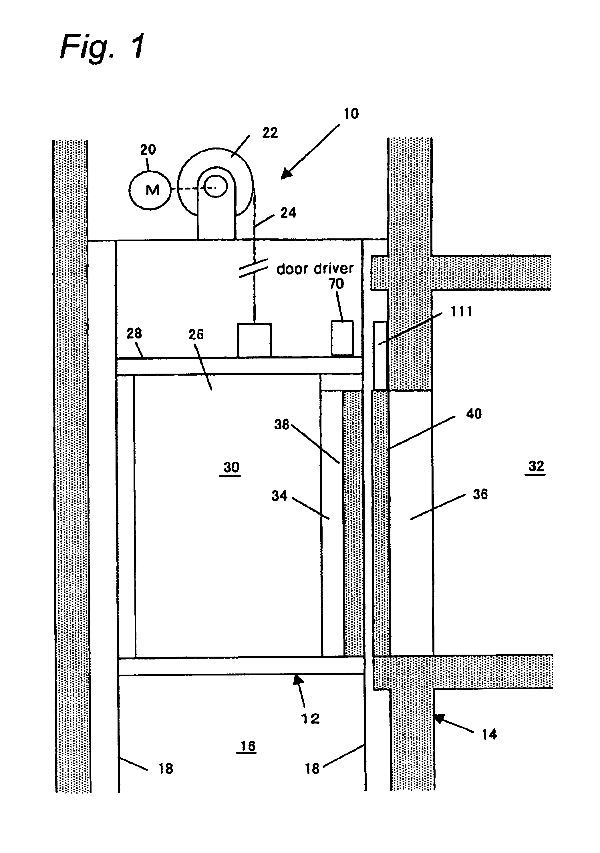
[0032]Referring to FIG. 1, there is shown an elevator system generally indicated by reference numeral 10. The elevator system 10 includes an elevating member 12 elevating within a vertical shaft 16 constructed in a building 14 so that it is guided by a plurality of vertical guide rails 18 extending on opposite side walls defining in part the shaft 16. A wire-winding device 22 with a driving motor 20 is secured at the top of the shaft 16. A wire 24 is wound at its one end around a drum of the wire-winding device 22 and connected at its opposite end with the elevating member 12. This causes, by driving the motor 24 of the wire-winding device 22, the elevating member 12 to move up and down within the shaft 16.

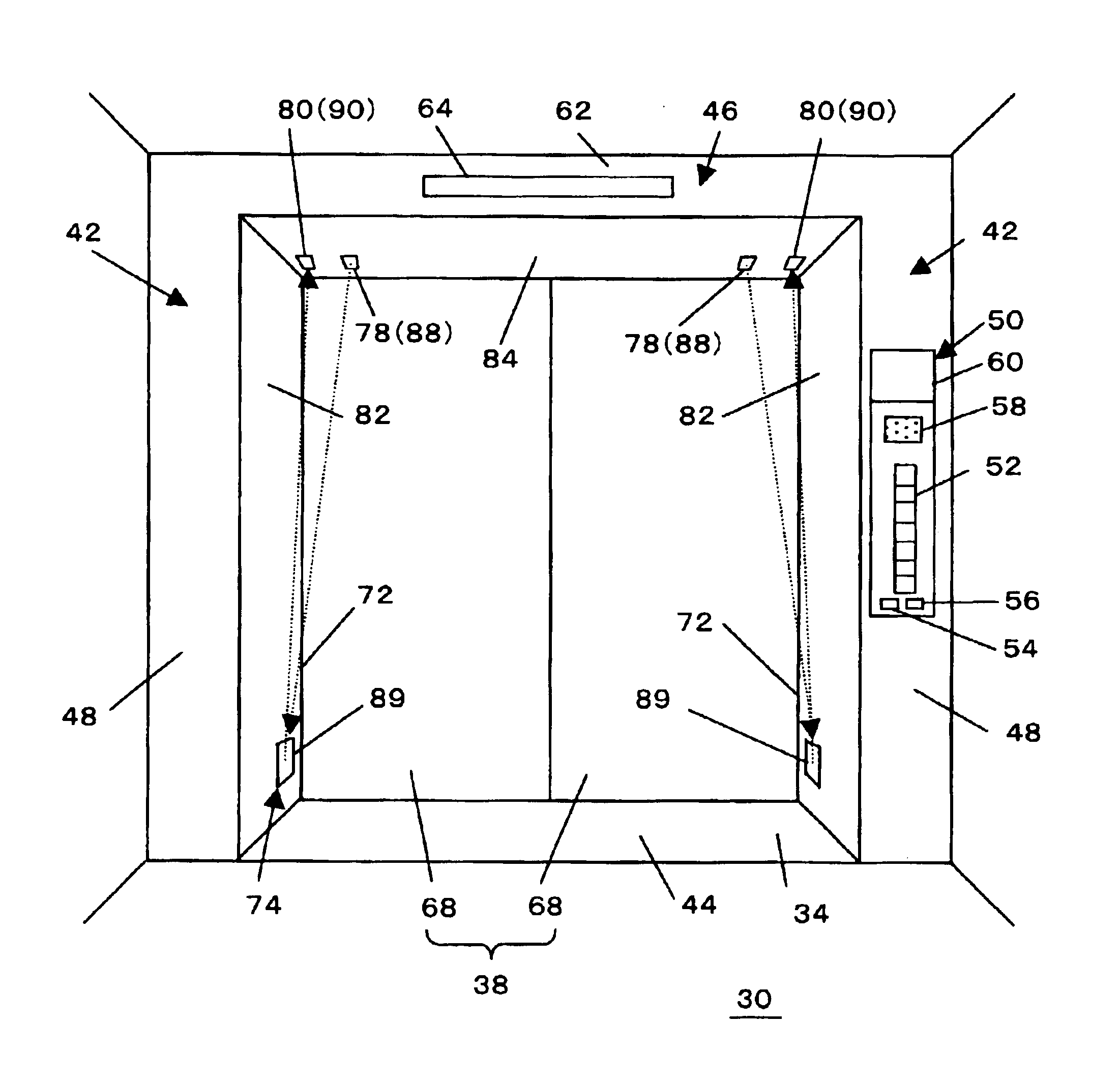
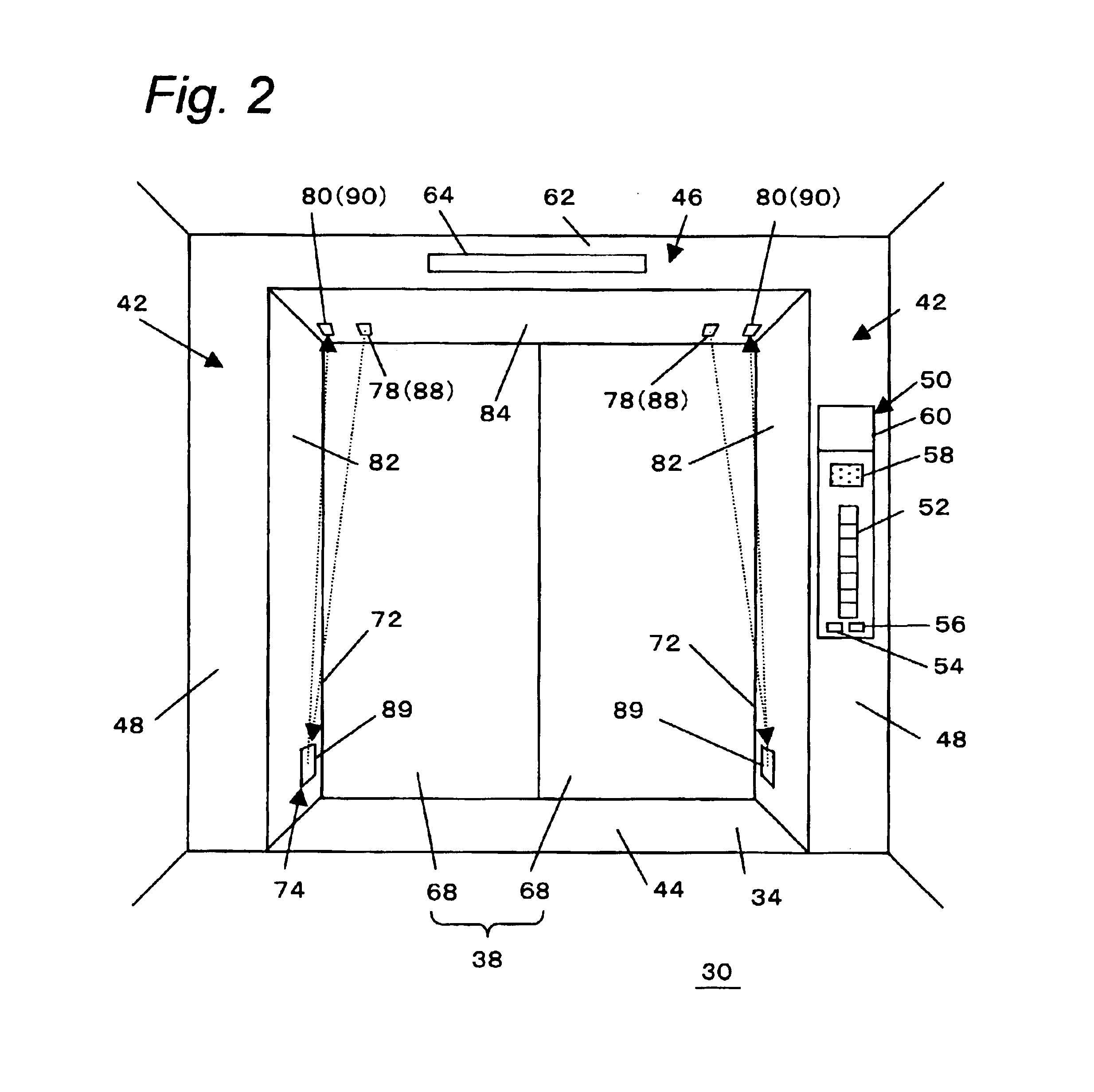
[0033]The elevating member 12 has an elevator cage 26 defining therein a room for the transportation of the passengers and cargoes and a frame 28 provided around the cage 26 for the structural reinforcement of the cage. For the connection and disconnection between the room 30 defi...

embodiment 2

[0053]In the safety installations shown in FIGS. 2 and 3, the first optical devices 78, 118 are mounted in and flush with the upper horizontal surface 84, 124 of the frame defining the upper end of the doorway 34, 36. As illustrated in FIG. 11, they may also be mounted in the vertical surface 82, 112 opposing to the light reflectors 89. The surfaces of the first optical devices 78, 118 facing to the doorway 34, 36 is arranged substantially flush with the vertical surface 82, 112.

embodiment 3

[0054]Although the light emitter 88 and the light receiver 90 are used as the first optical devices 78, 118 and the second optical devices 80, 120, respectively, in the above-mentioned embodiments, the light receiver 90 and the light emitter 88 may be used as the first optical devices 78, 118 and the second optical devices 80, 120, respectively.


PUM


Abstract

A sliding door system has a pair of horizontally opposed vertical surfaces defining therebetween an opening, an upper horizontal surface connecting uppermost ends of the vertical surfaces, a lower horizontal surface connecting lowermost ends of the vertical surfaces, and a door moving horizontally to open and close the opening. The sliding door system also includes a first optical device having a light emitter for emitting light, a second optical device having a light detector for detecting the light, and a light reflector for reflecting the light emitted from the light emitter to the light receiver. The light reflector is positioned in at least one of the horizontally opposed vertical surfaces. The first and second optical devices are positioned in the upper horizontal surface.

Description

BACKGROUND OF THE INVENTION[0001]1) Technical Field of the Invention[0002]The present invention relates to a sliding door system, and in particular relates to the sliding door system used for any equipment and facility such as an elevator system and an automatic sliding door system in a building and automobile.[0003]2) Description of Related Arts[0004]There have been disclosed various elevator systems each equipped with a safety installation for preventing any members such as clothes from being drawn into a small gap defined between a slide door and a fixed wall adjacent to the door when the door opens a doorway into or out of an elevator cage. Among others, the Japanese Patent Publication No. 63-66084 (A) discloses such a safety system, in which a vertical recess is formed at a vertically extending corner edge between one vertical wall defining the doorway and the other vertical wall adjacent to the opening / closing door. A pair of a light emitter and receiver are provided at a top ...

Claims


Application Information

Patent Timeline
IPC IPC(8): B66B13/26B66B13/24B66B13/28
CPCB66B13/26
Inventor SHIKAI, MASAHIRONAKASHIMA, TOSHIROTAKASHIMA, KAZUO
Owner MITSUBISHI ELECTRIC CORP
Why Eureka
Try Eureka