Media conveying mechanism

a media conveying and media technology, applied in the direction of thin material handling, article separation, registering devices, etc., can solve the problems of unfavorable media conveying speed and unnecessary idle of image-processing devices, and achieve the effect of improving the speed of media conveying

Inactive Publication Date: 2005-11-08
MULLER CAPITAL
View PDF12 Cites 30 Cited by
  • Summary
  • Abstract
  • Description
  • Claims
  • Application Information

AI Technical Summary

Benefits of technology

[0005]In view of the aforesaid disadvantages, the primary object of the invention is to provide a media conveying mechanism for use on media data recorders such as copiers, facsimile machines, multi-functional peripherals and the like to effectively improve media conveying speed.
[0007]During operation, first, the pickup roller catches and rolls the media into the media-conveying path. Next, the first clutch is pressed by the media to stop the operation of the pickup roller, and the intermediate roller continuously conveys the paper. When the sensor detects the front edge of the paper, the delivery roller rotates in the direction contrary to the intermediate roller so that the front edge of the paper may be aligned before arriving the delivery roller. The aligned paper is transported to leave the mechanism by the delivery roller and the intermediate roller; finally the paper is caught and discharged outside the mechanism by a discharge roller. When the rear edge of the paper departs from the first clutch, the first clutch returns to its original condition to continuously drive the pickup roller to fetch the next paper. Compared with the conventional techniques that convey the next media only after the paper has completely departed from the media mechanism, the mechanism of the invention can start conveying operation for the next paper when the rear edge of the current paper departs from the first clutch. Thus media conveying time is effectively reduced, and media-conveying speed greatly improves.

Problems solved by technology

This causes unnecessary idling of the image-processing device 140 or other printing conveying modules.
This is not efficient.

Method used


Image

  • Media conveying mechanism
  • Media conveying mechanism
  • Media conveying mechanism

Examples


Embodiment Construction

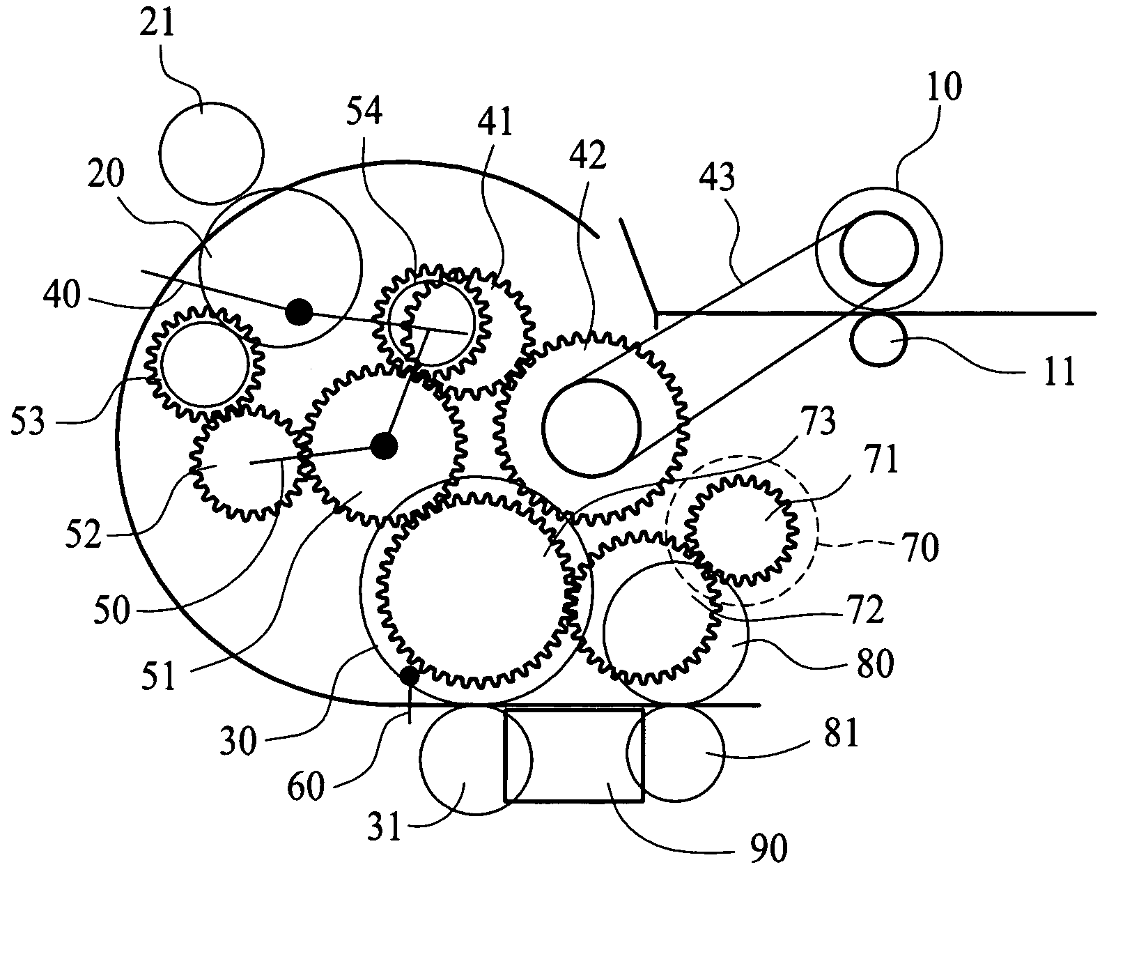
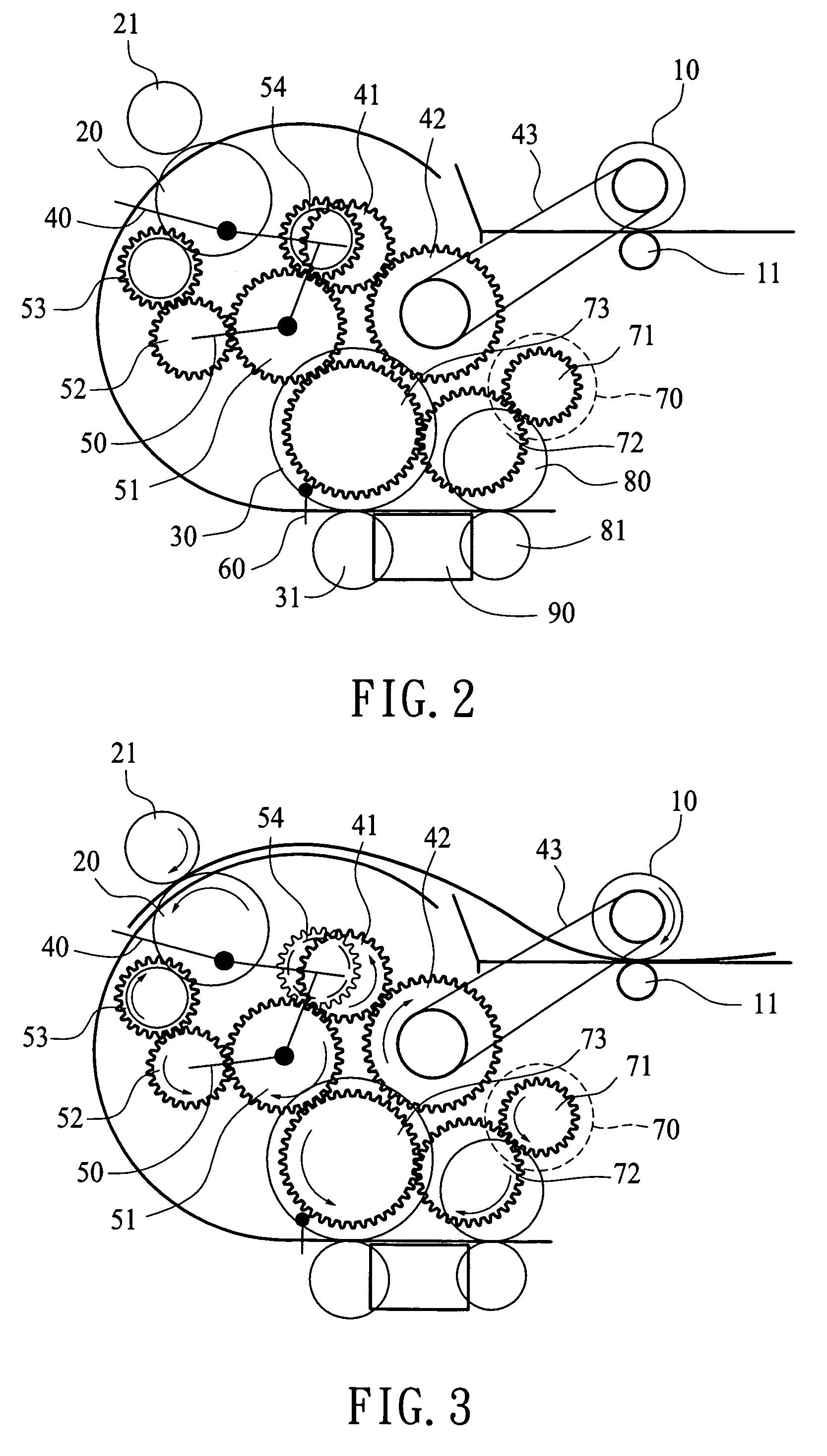
[0012]The media conveying mechanism according to the invention is installed in media data recorders for conveying a selected number of papers. It mainly aims to speed up media conveying speed.

[0013]Refer to FIG. 2 for the basic structure of the media conveying mechanism of the invention. It has a media conveying path, along the moving direction of media 200, there are a pickup roller 10, an intermediate roller 20, a delivery roller 30 and a discharge roller 80 disposed in this order. There is an auxiliary pickup roller 11 installed on a location corresponding to the pickup roller 10, and spaced from the pickup roller 10 at a selected distance to couple with the pickup roller 10 to catch papers 200 of different thickness. There is also an auxiliary intermediate roller 21 installed on a location corresponding to the intermediate roller 20 and spaced from the intermediate roller 20 at a selected distance to couple with the intermediate roller 20 to catch papers 200 of different thickne...


PUM


Abstract

A media conveying mechanism located in a media data recorder for conveying media mainly includes a driving motor to provide driving power needed. A first clutch to control the operation of a pickup roller. A second clutch to control rotation direction of an intermediate roller, a sensor to detect the conveying process of the media and control the operation of the second clutch. By deploying the two clutches, conveying quantity of the media in a unit time period can be effectively improved.

Description

FIELD OF THE INVENTION[0001]The present invention relates to a media conveying mechanism adopted for use on media data recorders such as printers, facsimile machines, scanners and the like to convey media and particularly to a media conveying mechanism to greatly improve media conveying speed.BACKGROUND OF THE INVENTION[0002]Media data recorders are widely used in individual and industrial businesses such as exchange of letters and documents, performing document scanning, printing, copying or facsimile operations. There is a wide variety of media data recorders, such as ink-jets, lasers and impact printers, plotters, scanners, copiers, multi-functional peripheral (MFP), and the like. Printing quality and operation efficiency of the media data recorders have always been key development focuses in this industry.[0003]The present media data recorders, such as copiers, mostly employ roller mechanisms to convey media in the operations of media feeding, scanning, printing or discharging. ...

Claims


Application Information

Patent Timeline
Patent Type & Authority Patents(United States)
IPC IPC(8): B65H3/06B65H5/06
CPCB65H3/0669B65H5/06B65H2403/422B65H2403/722B65H2220/09
Inventor SU, YU-JEN
Owner MULLER CAPITAL
Why Eureka
Try Eureka