Anti-wicking catcher arrangement for a solvent ink printhead

Inactive Publication Date: 2005-11-08
EASTMAN KODAK CO
View PDF12 Cites 13 Cited by
  • Summary
  • Abstract
  • Description
  • Claims
  • Application Information

AI Technical Summary

Benefits of technology

[0006]This need is met by the anti-wicking catcher design according to the present invention, wherein ink wicking outward on the catcher face is eliminated. The present invent

Problems solved by technology

Solvent inks, having a much lower surface tension (approximately 24 dynes/cm) crea

Method used


Image

  • Anti-wicking catcher arrangement for a solvent ink printhead
  • Anti-wicking catcher arrangement for a solvent ink printhead
  • Anti-wicking catcher arrangement for a solvent ink printhead

Examples


Embodiment Construction

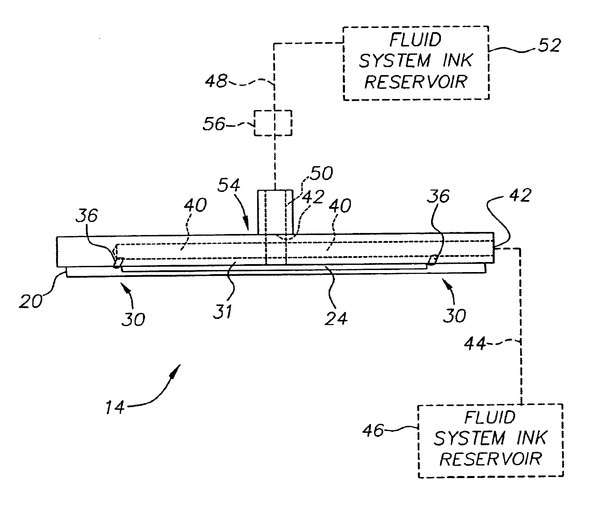
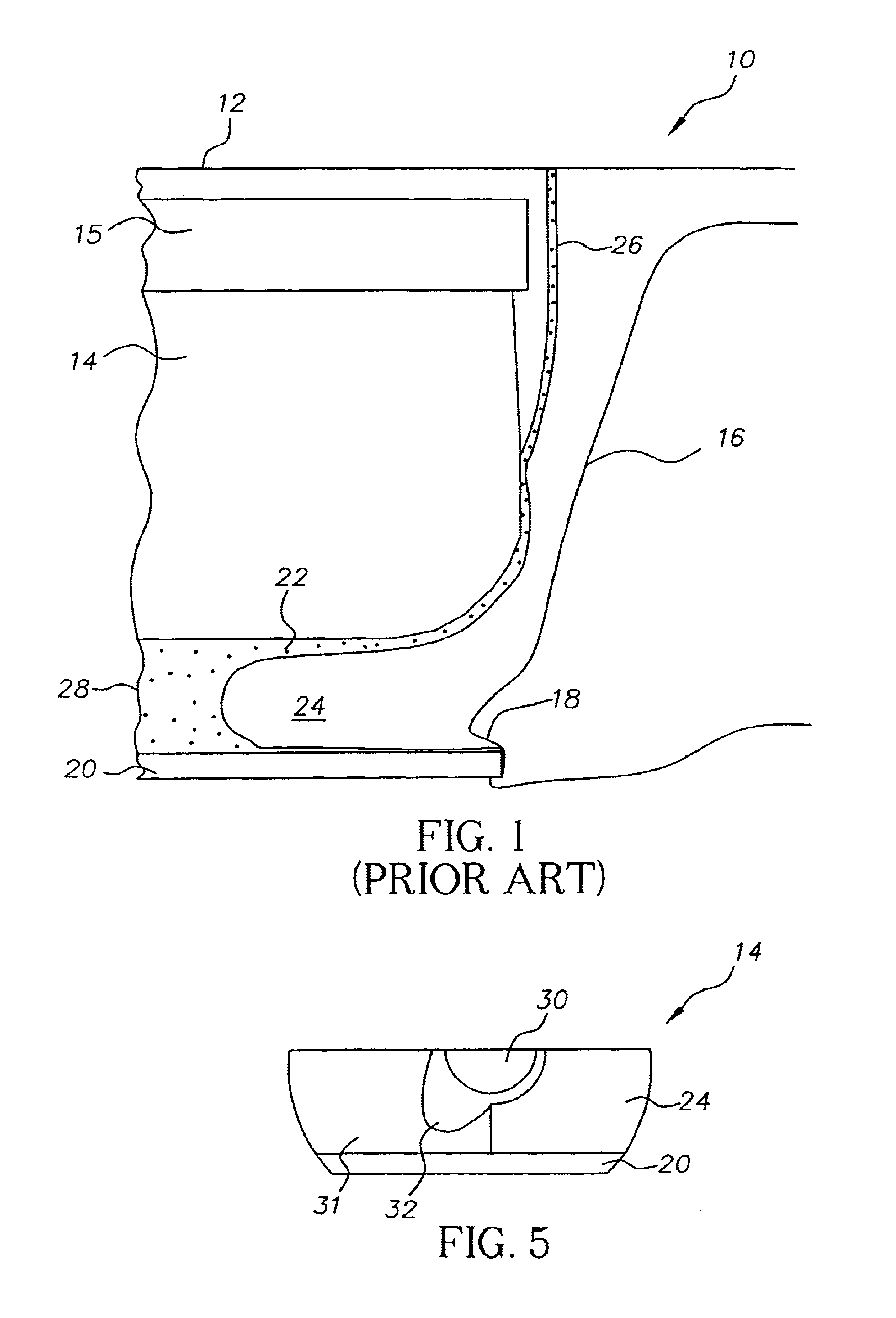
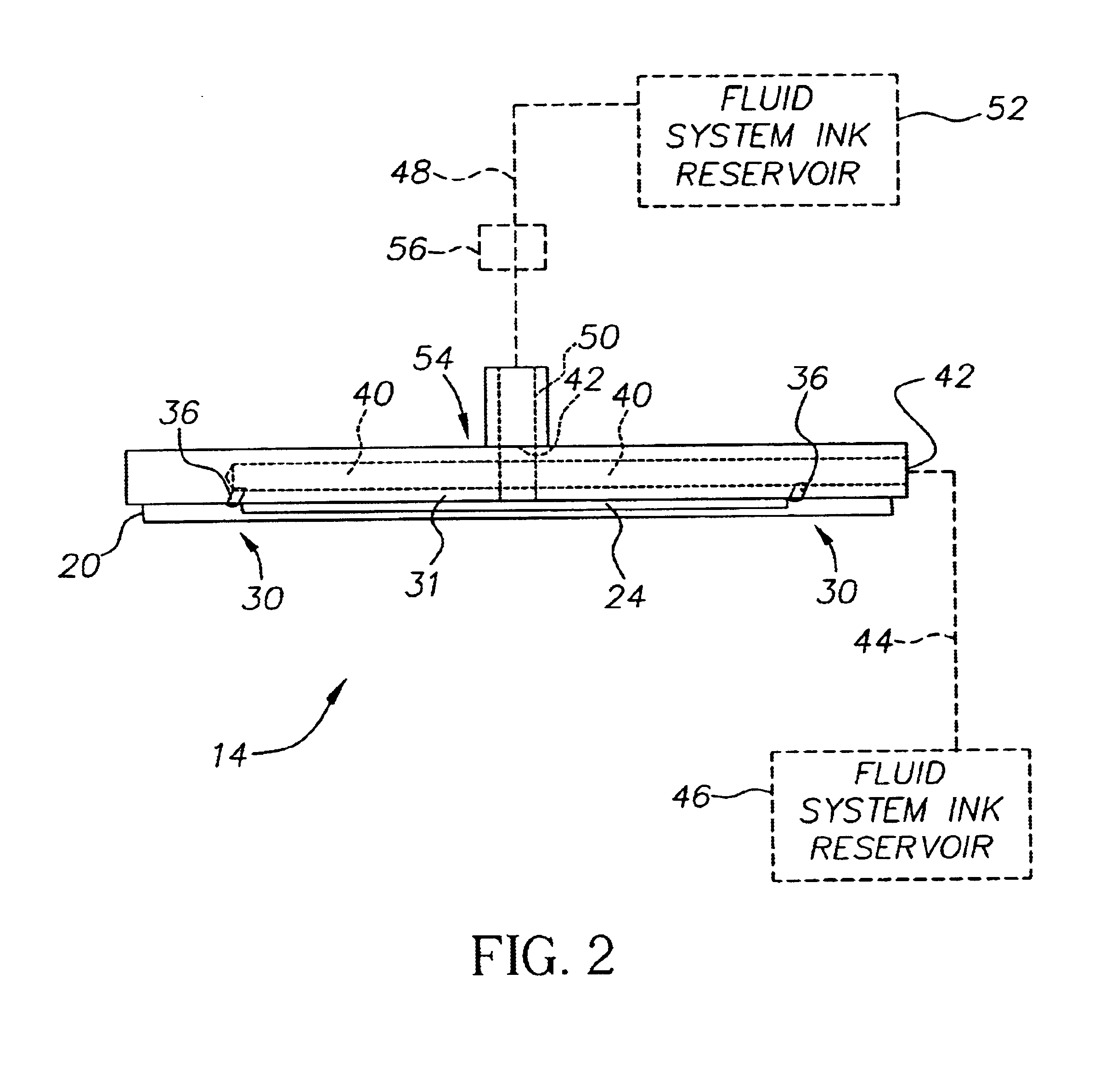
[0013]The present invention proposes an improved catcher design for controlling the flow of unprinted ink and eliminating wicking our of the catcher throat. In existing printheads, ink drops are deflected onto the face of the catcher. The ink then flows down the face of the catcher, rounding the radius at the bottom of the catcher and entering the catcher throat, from where it can be evacuated. With low surface tension inks, such as solvent based inks, there can be some lateral spreading of the ink as it flows down the catcher face, due to the wicking nature of such inks. An air-ink interface forms inside the catcher throat, with ink filling the inner portion of the catcher throat. As ink is being evacuated from the catcher, the air-ink interface, rather than remaining static, moves in and out, causing air bubbles to occasionally be drawn into the ink. In certain operating conditions, this air-ink interface can become unstable as a result of ingesting air, causing ink to spit out of...


PUM


Abstract

A catcher design is provided wherein vacuum channels are added to both sides of the catcher to remove ink from the face of the catcher and from the eyelid seal. An additional fluid port on the catcher allows the additional vacuum channels to maintain an increased level of vacuum. A restriction on the catcher line balances the fluid flow between the catcher and the additional vacuum channels. A scoop can be machined into the catch pan to remove fluid from below the catcher face. A manifold can be used to maintain a vacuum source for the catcher throat and the additional channels, while pulling the unprinted ink back to the fluid system. Finally, a wider eyelid seal can allow purge fluid used during shutdown to clear the channels.

Description

TECHNICAL FIELD[0001]The present invention relates to continuous ink jet printing systems and, more particularly, to a catcher design for a solvent based ink printing system, to prevent ink from wicking out of the catcher throat.BACKGROUND ART[0002]Ink jet printing systems are known in which a printhead defines one or more rows of orifices which receive an electrically conductive recording fluid from a pressurized fluid supply manifold and eject the fluid in rows of parallel streams. Printers using such printheads accomplish graphic reproduction by selectively charging and deflecting the drops in each of the streams and depositing at least some of the drops on a print receiving medium, while others of the drops strike a drop catcher device.[0003]Over the years, a number of inkjet printers using binary array continuous inkjet printing have been developed, with continuing improvements in speed, reliability, and ease of use. These printers are used in a variety of print applications, o...

Claims


Application Information

Patent Timeline
IPC IPC(8): B41J2/185
CPCB41J2/185B41J2002/1853
Inventor WEST, KENNETH J.FRAZIER, JAY D.HULIBA, DAVID A.BOWLING, BRUCE A.RIKE, CHARLES D.
Owner EASTMAN KODAK CO
Why Eureka
Try Eureka