Method of recording and reproducing an optical recording medium

a technology of optical recording medium and optical recording medium, which is applied in the direction of digital signal error detection/correction, recording signal processing, instruments, etc., can solve the problems of deviation of the beam from the corresponding track, difficulty in accurately reading the signal recorded, and eccentricity

Inactive Publication Date: 2005-11-08
DIGITAL CACHE LLC
View PDF15 Cites 30 Cited by
  • Summary
  • Abstract
  • Description
  • Claims
  • Application Information

AI Technical Summary

Problems solved by technology

In manufacturing the optical disc, warp may occur during a resin-injection and hardening process, and eccentricity may occur despite the center hole in the disc.
Since this makes it difficult to accurately read the signal recorded on a desired track, a standard for the CD and DVD is determined with respect to the amount of deviation, and a tracking servo is performed so that an optical beam constantly follows the desired track even if eccentricity occurs.
Meanwhile, deviation of the beam from the corresponding track occurs due to the inclination of the disc, as well as the eccentricity of the disc.
This disc inclination may occur due to a mechanical problem such as a placement error when the disc is placed on a spindle motor.
However, the DVD, which is a high-density optical application device, has a narrow track pitch, and thus has a small radial tilt margin for a zitter.
Accordingly, if only a small tilt occurs, i.e., if the disc is inclined only slightly, a detrack causing the beam to go over to a neighboring track occurs, and this cannot be sufficiently corrected by the tracking servo alone.
In this case, data cannot be accurately read out from the disc during reproduction.
Also, data cannot be accurately written on the corresponding track during recording, and this causes dual distortion to occur in the reproduced data.
This method, however, has a drawback in that an increase in the size of the set results in a loss of efficiency.
During focus control, i.e., focus servo, if an optical focus deviates from the disc surface (hereinafter referred to as defocus), the quality of the recorded or reproduced data deteriorates, and this causes the operation of the system to become unstable.
Meanwhile, in the optical disc such as the DVD-RAM, whereby data can be recorded on both the lands and the grooves, the focus offsets are different due to the depth difference between the land and the groove, and thus defocus may occur even if the focus error signal is zero.
Specifically, since the offset has not been adjusted due to the depth difference between the land and the groove even if focusing is performed, focusing may not be effected when it is applied to the track of the groove as it is.
At this time, the defocus state cannot be identified only by the focus error signal, and this causes the zitter characteristic to deteriorate and a bit error rate (BER) to become larger.
If the recording is performed in this state, the recording characteristics of the land and the groove may be changed, so that the quality of the recorded or reproduced data deteriorates, and thus the operation of the system becomes unstable in the same manner as described above.

Method used


Image

  • Method of recording and reproducing an optical recording medium
  • Method of recording and reproducing an optical recording medium
  • Method of recording and reproducing an optical recording medium

Examples


first embodiment

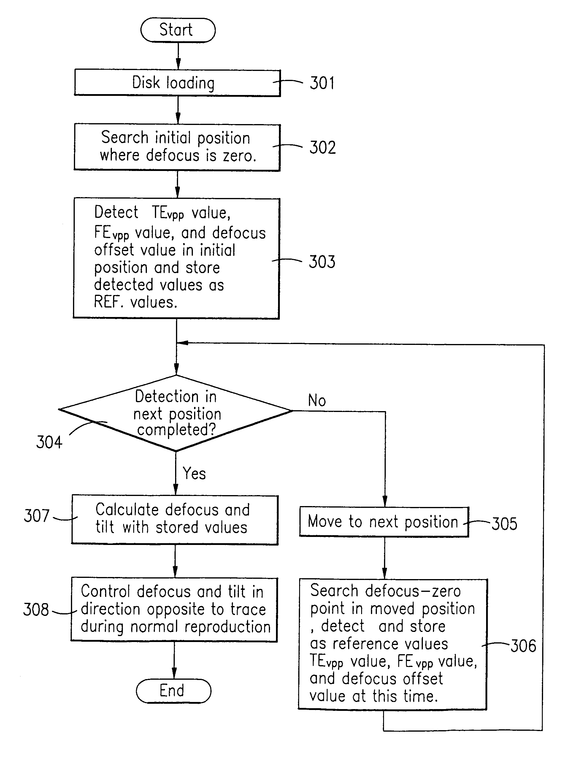
[0093]According to the first embodiment of the present invention, the tilt detection is respectively performed in a plurality of determined positions on the inner and outer peripheries of the disc when the system is initialized.

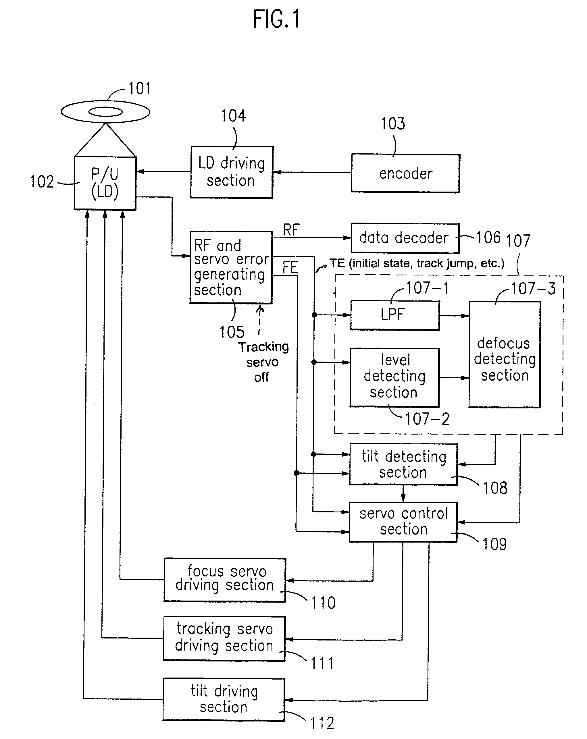
[0094]For instance, if the disc is loaded, the RF and servo error generating section 105 detects the tracking error signal and the focus error signal in the free running state in which only the focus servo is turned on, and outputs the detected tracking and focus error signals to the tilt detecting section 108 and the servo control section 109. The tracking error signal is detected by the eccentric disc if the optical pickup 102 is fixed and only the optical disc 101 is rotated in the state in which the focus servo is turned on and the tracking servo is turned off.

[0095]FIGS. 6 to 8 are graphs exemplifying that the tracking error signal and the focus error signal, which are detected in the free running state in which the focus servo is turned on and the track...

second embodiment

[0112]In the second embodiment of the present invention, the detection of the tilt is performed in the free running state, when the system is initialized. Specifically, when a disc is loaded in the free running state in which only the focus servo is turned on, the RF and servo error generating section 105 detects a tracking error signal and outputs it to the tilt control section 108 and the servo control section 109.

[0113]At that time, if the tilt does not occur, the center value of the tracking error signal has the same value on the inner or outer peripheries of the disc as shown in FIG. 9A.

[0114]By contrast, if the tilt occurs, the center offset of the tracking error signal is produced as shown in FIG. 9B. In other words, the center value of the tracking error signal detected on the inner and outer peripheries differs depending on the tilt.

[0115]Therefore, if the center value of the tracking error signal is detected at a predetermined position of the inner and outer peripheries in...


PUM

PropertyMeasurementUnit
timeaaaaaaaaaa
sizeaaaaaaaaaa
recording densityaaaaaaaaaa

Abstract

A method of recording and reproducing an optical recording medium which detects a defocus and a tilt of the optical recording medium and compensates the detected defocus and tilt in a high-density optical recording medium. In a free running state in which only a focus servo is turned on, the amount of defocus offset that corresponds to a maximum level of a tracking error signal is detected in a plurality of positions on inner and outer peripheries of a disc, and a tilt-zero in the respective position is detected and stored, so that a tilt servo and a focus servo are performed with the value stored in the corresponding position during an actual recording / reproduction. The method can prevent the deterioration of quality of data due the defocus during recording / reproduction, enabling real time recording by quickly stabilizing the focus servo, and stable operation of the system. Also, the method can follow corresponding tracks with a rapid stabilization of servo during a search or seek, and detect and compensate for the tilt stably and accurately in the high-density optical disc. The method can also prevent the deterioration of quality of data and a detrack due to the tilt during recording / reproduction, and thus achieve stable operation of the system.

Description

BACKGROUND OF THE INVENTION[0001]This non-provisional application claims priority under 35 U.S.C. § 119(a) on Patent Application Nos. P1999-17870, P1999-18895, and P1999-1899 filed in Korea on May 18, 1999, May 25, 1999, and May 25, 1999, respectively, which are herein incorporated by reference.FIELD OF THE INVENTION[0002]The present invention relates to an optical recording medium, and more particularly to a method of detecting and compensating for defocus and tilt of the optical recording medium.DESCRIPTION OF THE RELATED ART[0003]Generally, an optical recording medium is classified into three types, that is, a read only memory (ROM) type, a WORM type that is writable once only, and a rewritable type that is repeatedly writable.[0004]Examples of the repeatedly rewritable optical recording medium are on optical disc, a rewritable compact disc (CD-RW) and a rewritable digital versatile disc (DVD-RW, DVD-RAM, and DVD+RW).[0005]A rewritable optical disc such as the DVD-RAM has signal ...

Claims


Application Information

Patent Timeline
Patent Type & Authority Patents(United States)
IPC IPC(8): G11B7/00G11B7/095G11B7/007G11B7/09
CPCG11B7/094G11B7/0945G11B7/0956G11B7/00718
Inventor PARK, SANG ONHONG, SEONG PYO
Owner DIGITAL CACHE LLC
Why Eureka
Try Eureka