
Multitone frequency hop communications system

a multi-frequency hop and communications system technology, applied in the direction of transmission, electrical equipment, etc., can solve the problem that the multi-frequency hop uses only a relatively small fraction of the available tones, and achieve the effect of low probability of interception

Inactive Publication Date: 2005-11-08
HARRIS CORP
View PDF7 Cites 16 Cited by
  • Summary
  • Abstract
  • Description
  • Claims
  • Application Information

AI Technical Summary

Benefits of technology

[0016]Multitone frequency hop is an improved spread-spectrum communications approach which builds on both traditional frequency hopping systems and the featureless waveform system of Storm and Zuelsdorf to achieve a communications system which combines very low probability of interception with minimal interference between competing “friendly” transmitters. In the multitone frequency hop system Nt tones out of N are assigned pseudo-randomly to define a data symbol. In addition, the tone phases are determined pseudo-randomly to give a noise-like transmitted waveform.
[0017]Multitone frequency hop begins with a frequency domain input signal generally analogous to that described by Storm and Zuelsdorf. However, rather than utilizing the entire spectrum of frequency tones available, as would occur in the Storm and Zuelsdorf direct sequence modulation, multitone frequency hop uses only a relatively small fraction of the available tones. For example, 64 tones out of a possible 1024 frequency channels may be sent simultaneously. As will be readily apparent, this reduces the number of collisions between desired and interfering tones hopping to the same frequency at the same time to a tolerable level.
[0018]Multitone frequency hop also generates a low probability of intercept signal because of the relatively large number of tones with pseudo-randomized phases which are sent for each increment of information transmitted. As already explained, ordinary frequency hopping, with only one tone sent at a time is relatively easy to intercept because all the transmitted energy is concentrated in one frequency channel. In contrast, multitone frequency hop reduces the density of the transmitted signal power by the number of tones used for a particular instantaneous transmission. For example, the use of 64 tones—i.e., with the transmitted energy spread over such 64 frequencies—reduces the spectrum density of the transmitted signal by 18 db compared with ordinary frequency hopping.

Problems solved by technology

However, rather than utilizing the entire spectrum of frequency tones available, as would occur in the Storm and Zuelsdorf direct sequence modulation, multitone frequency hop uses only a relatively small fraction of the available tones.

Method used


Image

  • Multitone frequency hop communications system
  • Multitone frequency hop communications system
  • Multitone frequency hop communications system

Examples


Embodiment Construction

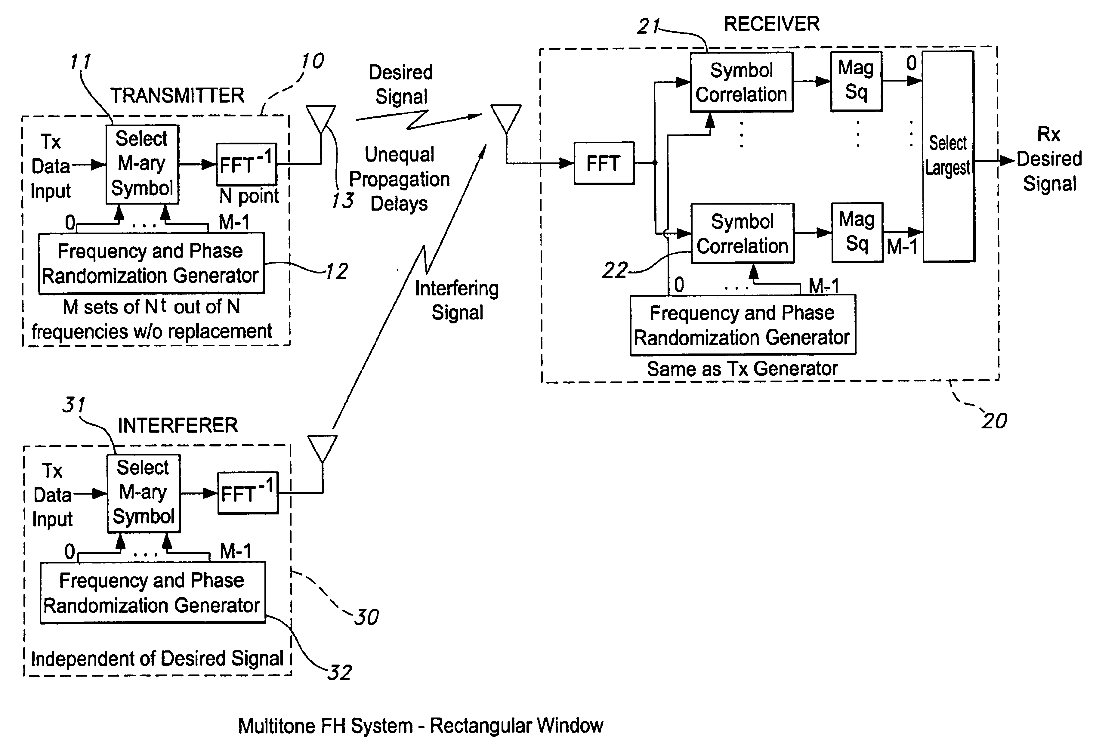
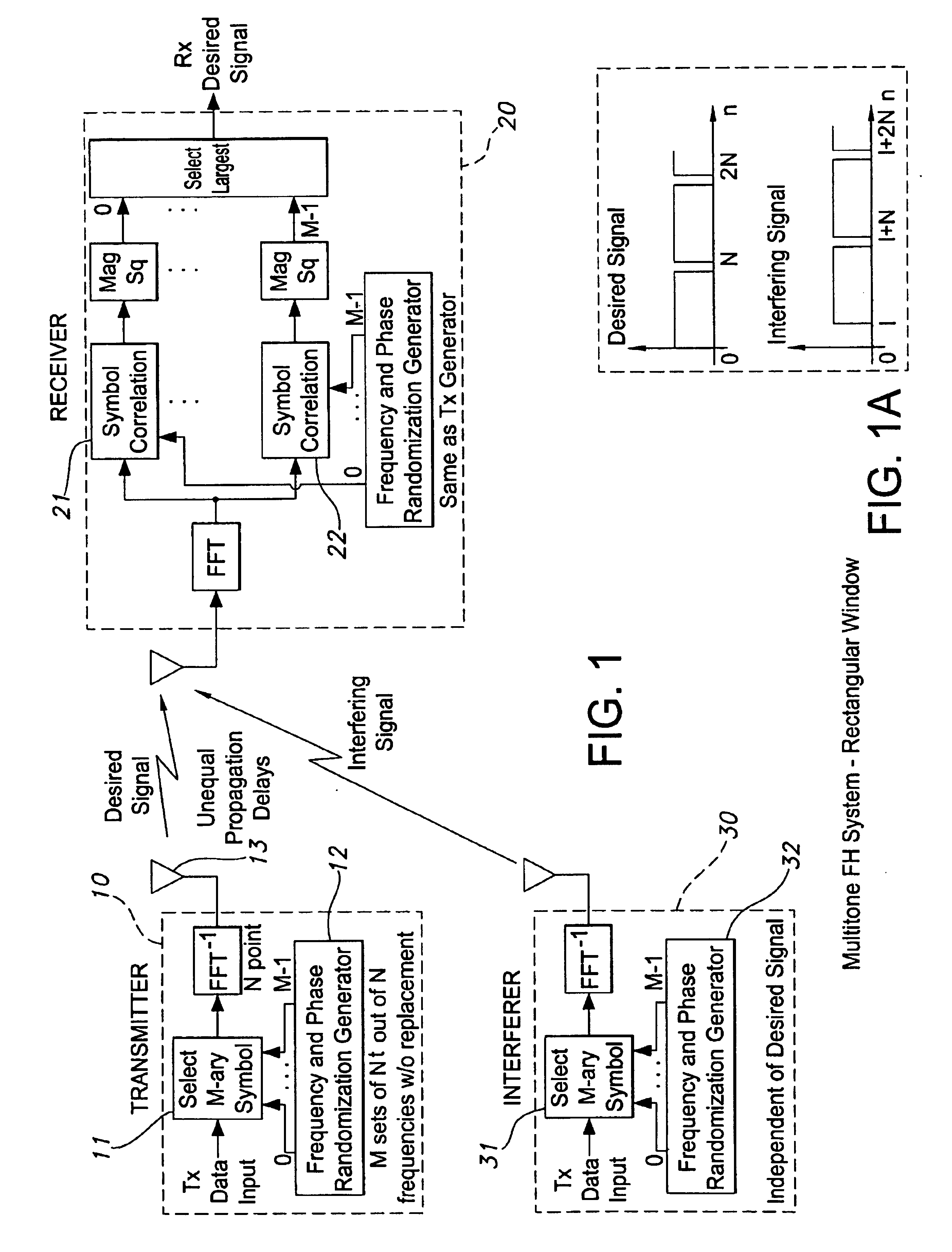
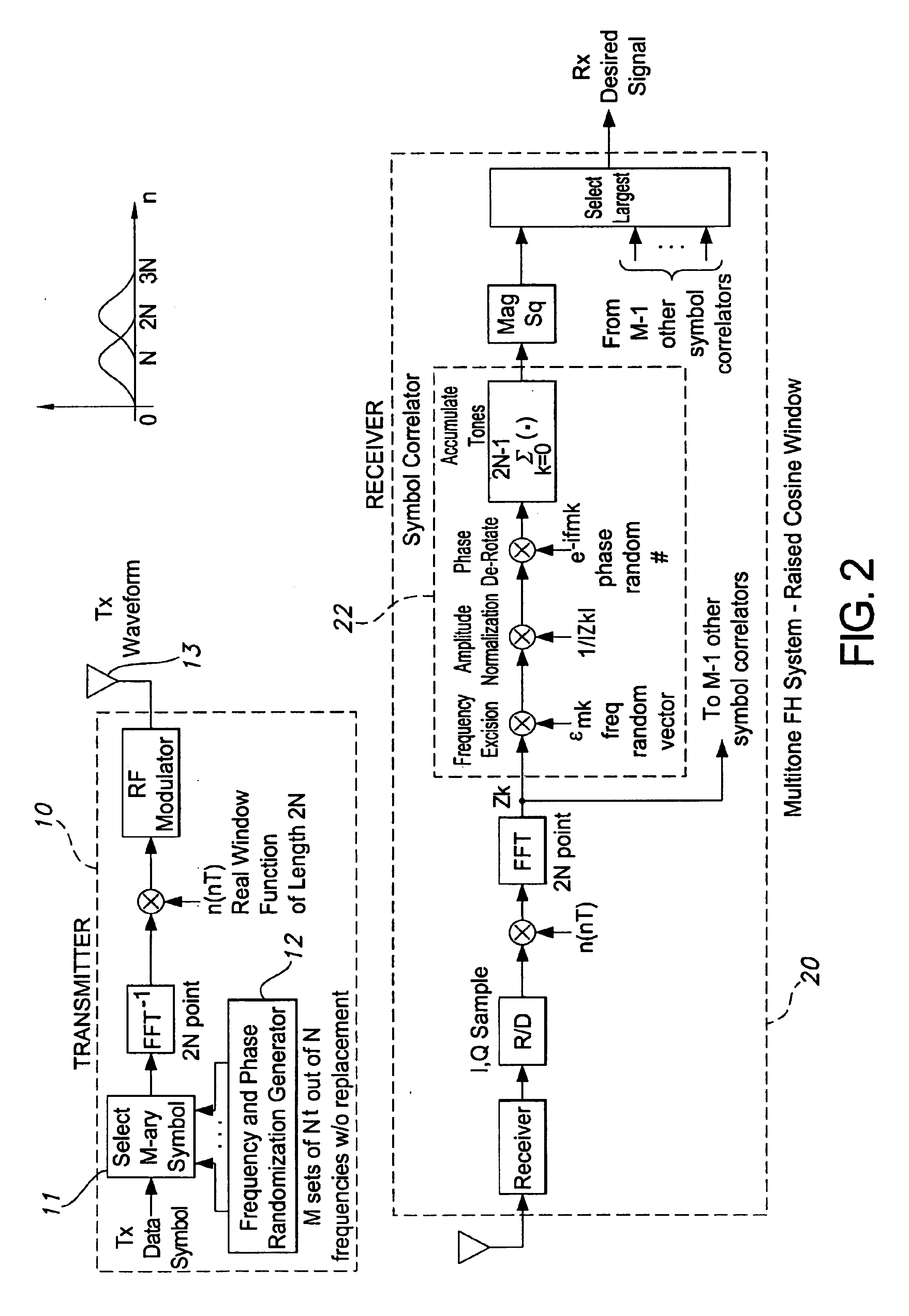
[0030]FIG. 1 shows an embodiment of the multitone frequency hop system in which a receiver 20 receives both a desired signal from transmitter 10 and an interfering signal from transmitter 30, both transmitters being of the same type but with different waveform randomizations. Transmitter 10 sends a sequence of M-ary data symbols corresponding to digitized input data where each symbol represents one of the M possible states of the input data. At each successive timing interval for the transmitter, as determined by well-known timing methodologies, the data symbol to be transmitted (and corresponding to the increment of digitized input data to be transmitted during that timing interval) is selected by selector 11. Each of the M-ary data symbols is coded during a given timing interval by selecting Nt tones out of a set of N available tones. The frequencies of the Nt tones representing each of the M-ary data symbols are pseudo-randomly chosen by frequency and phase randomization generato...


PUM


Abstract

An improved spread spectrum communications system is disclosed in which M-ary symbols are defined corresponding to each state of digital data to be transmitted and in which each of those M-ary symbols are represented by a plurality of tones selected from a set of N frequencies. A different plurality of tones out of the set N is established to represent each of the M-ary symbols during each successive timing interval, with selection of the tones comprising each such plurality of tones being determined in accordance with a known coding pattern. Phasing of the tones comprising each such plurality is also determined in accordance with a known coding sequence. After selection of the symbol corresponding to the data to be transmitted during a given timing interval, the frequency domain representation of the plurality of tones corresponding to that symbol is converted to the time domain for transmission. That time domain signal is converted back to the frequency domain by the receiver and the resultant signal processed by M-ary signal correlators synchronized with coding established by the transmitter to determine the transmitted symbol.

Description

FIELD OF THE INVENTION[0001]This invention relates to broad-band communications systems in general, and more particularly to such a system where security of the transmitted intelligence is enhanced and the likelihood of interference at the selected receiver from other transmitters using the same frequency spectrum is materially decreased.BACKGROUND OF THE INVENTION[0002]Spread spectrum communications systems have been used in a variety of fields. In a communications system of this type, the transmitted bandwidth is much greater than the bandwidth or bit-rate of the information to be transmitted. Additionally, the carrier signal is modulated by some other function than the information being sent. At its essence, spread spectrum communications represents the art of expanding the bandwidth of a signal, transforming that expanded signal, and recovering the desired signal by remapping the received spread spectrum into the original information bandwidth. In general, the purpose of pursuin...

Claims


Application Information

Patent Timeline
Patent Type & Authority Patents(United States)
IPC IPC(8): H04B1/69H04B1/713
CPCH04B1/713
Inventor DUNN, JAMES G.
Owner HARRIS CORP
Learn More