Method and system for enhancing the performance of a fixed focal length imaging device

a fixed focal length and imaging device technology, applied in the field of imaging systems, can solve the problems of less than optimal signal-to-noise ratio, less than desirable situation, and inability to achieve the minimum image resolution designed, so as to enhance the performance of the fixed focal length imaging device, the average signal-to-noise ratio of the output pixels may be improved.

Inactive Publication Date: 2005-11-08
BAE SYST INFORMATION & ELECTRONICS SYST INTERGRATION INC
View PDF8 Cites 7 Cited by
  • Summary
  • Abstract
  • Description
  • Claims
  • Application Information

AI Technical Summary

Benefits of technology

[0010]The present invention is directed to enhancing the performance of a fixed focal length imaging device. An input group of pixels obtained using an imager is converted into an output group of pixels having an equal or lower pixel count. During the conversion process, the average signal-to-noise ratio of the output pixels may be improved.
[0013]It is another feature of the present invention that a change in distance between the imager and an object can be used to dynamically adjust the number of output pixels formed.

Problems solved by technology

If these imaging systems are used to image objects at a distance in excess of their maximum design distance, they will not be able to achieve their designed minimum image resolution.
When this occurs, these imaging systems will have an achievable image resolution in excess of their designed minimum image resolution and a less than optimal signal-to-noise ratio.
This is a less than desirable situation when high speed data transmission or processing is required.

Method used


Image

  • Method and system for enhancing the performance of a fixed focal length imaging device
  • Method and system for enhancing the performance of a fixed focal length imaging device
  • Method and system for enhancing the performance of a fixed focal length imaging device

Examples


example application

of the Present Invention

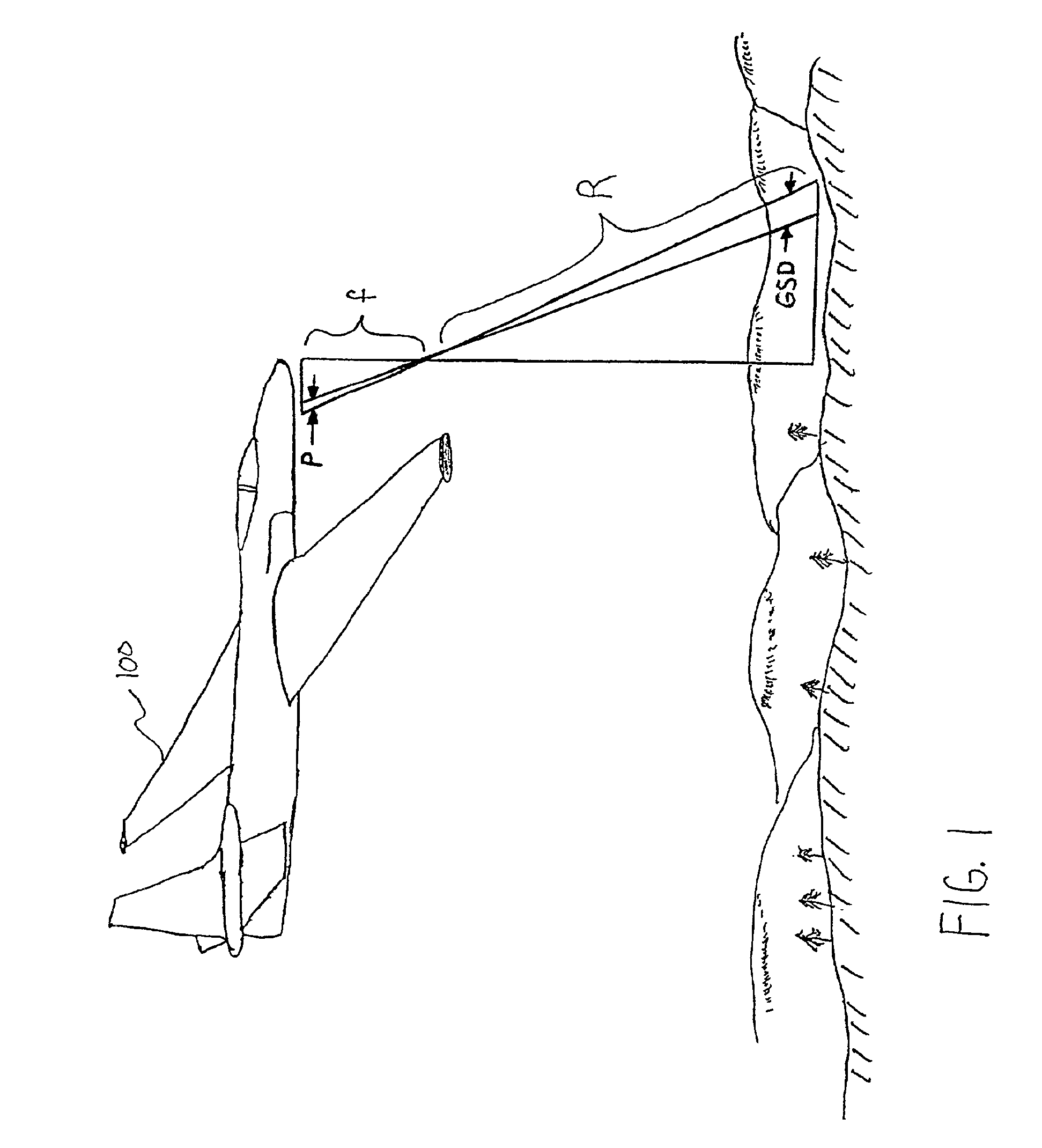
[0036]The present invention is particularly well adapted for use with an airborne imaging system. As will be described herein, the present invention can be used to enhance the performance of either a pan scan imager or a staring imager of a type typically used for tactical reconnaissance imaging. The present invention is described herein with reference to an airborne imaging system because that is a preferred use of the invention by the inventor. However, as will be apparent to a person skilled in the relevant art given the description of the invention herein, the present invention is not limited to being used only with an airborne imaging system. The present invention can be used to enhance the performance of any imaging device having a fixed focal length. The invention can also be used to convert a variable resolution image to a fixed resolution image.

[0037]As would be known to a person skilled in the relevant art, the resolution of an airborne imaging syst...

example system embodiment

of the Present Invention

[0051]FIG. 5 illustrates a system 500 for enhancing the performance of a fixed focal length imaging device. System 500 converts a group of five input pixels into a group of four output pixels. System 500 comprises a pixel receiving module 510, a pixel weighting module 520, and a pixel combining module 580.

[0052]Pixel receiving module 510 is typically coupled to the output of an imager (not shown). It may be coupled to a digital filter, however. Digital filters may be used to assure that no frequencies above those desired are present in the input pixels received by pixel receiving module 510. This is done to improve signal quality. Pixel receiving module 510 is shown as receiving five input pixels {Y1, Y2, Y3, Y4, Y5} from an input stream of pixels (not shown). Pixel receiving module 510 can receive and temporarily store more or less than five pixels. Pixel receiving module 510 can be a buffer.

[0053]Pixel weighting module 520 is coupled to pixel receiving modu...

example method embodiment

of the Present Invention

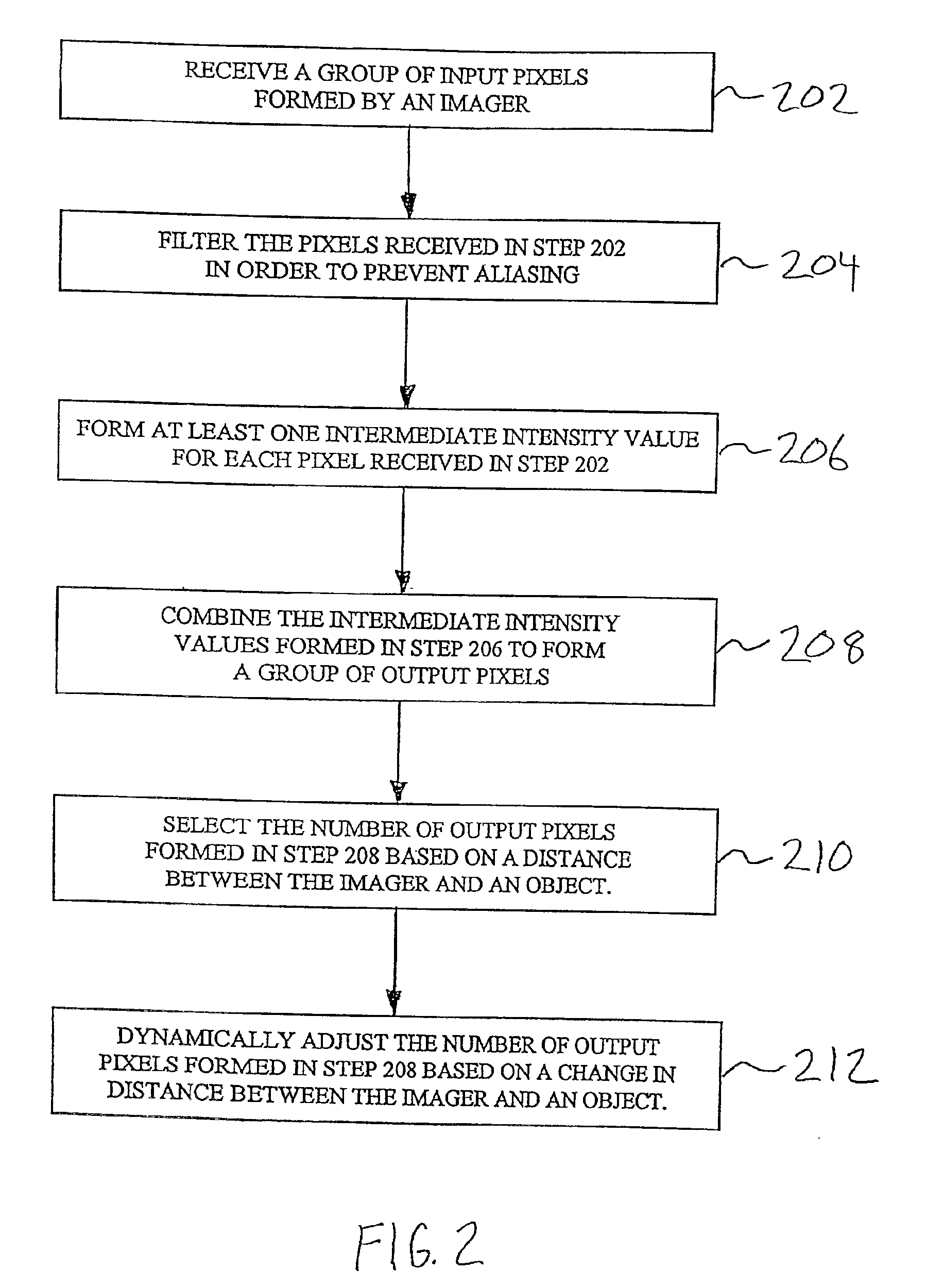
[0059]FIG. 2 illustrates a flowchart of a method for enhancing the performance of an imaging device having a fixed focal length according to the present invention. This method can be implemented using system embodiments of the present invention (e.g., system 500), and it is described with reference to the features illustrated in FIG. 5. As described below, the method comprises six steps, of which three steps are optional steps.

[0060]In step 202, a group of input pixels formed by an imager is received and temporarily stored in a memory, e.g., buffer 510. The group of input pixels received in step 202 is variable as described below (i.e., it is not necessarily five pixels as shown in FIG. 5). Typically, the received group of input pixels will be a contiguous series of pixels obtained by the imager.

[0061]In optional step 204, the pixels received in step 202 are filtered in order to prevent aliasing. Step 204 can be performed either before step 202 or after step ...


PUM


Abstract

A group of pixels obtained using an imaging device is converted into a group of pixels having an equal or lower count by receiving at least first and second input pixels having an initial intensity value, forming at least one intermediate intensity value from each of the first and second input pixels, and combining the intermediate intensity values formed from the first and second input pixels to form at least one output pixel. This allows the pixels formed to have improved signal-to-noise characteristics, and it reduces transmission rates. A feature of the present invention allows a distance between the imaging device and an object to be used to select the number of output pixels formed. Another feature of the present invention allows a change in distance between the imaging device and an object to be used to dynamically adjust the number of output pixels formed. A further feature of the invention allows a variable resolution image to be converted to a fixed resolution image.

Description

CROSS-REFERENCE TO RELATED APPLICATIONS[0001]Not applicable.STATEMENT REGARDING FEDERALLY-SPONSORED RESEARCH AND DEVELOPMENT[0002]Not applicable.REFERENCE TO MICROFICHE APPENDIX / SEQUENCE LISTING / TABLE / COMPUTER PROGRAM LISTING APPENDIX (submitted on a compact disc and an incorporation-by-reference of the material on the compact disc)[0003]Not applicable.BACKGROUND OF THE INVENTION[0004]1. Field of the Invention[0005]The present invention relates to imaging systems. More particularly, it relates to imaging devices having a fixed focal length.[0006]2. Related Art[0007]Many imaging systems have an imager that receives energy and converts the received energy into a form of data known as pixels. This pixel data can then be stored by these imaging systems for subsequent retrieval and processing and / or transmitted to a remote receiving station for storage and processing. Pixel data can be processed using known signal processing techniques. Improving the signal quality and / or reducing the da...

Claims


Application Information

Patent Timeline
Patent Type & Authority Patents(United States)
IPC IPC(8): G06T5/20
CPCG06T5/20
Inventor BLOSSER, ROBERT C.
Owner BAE SYST INFORMATION & ELECTRONICS SYST INTERGRATION INC
Why Eureka
Try Eureka