Data transfer control device, electronic equipment, and power supply switching method

a control device and data transfer technology, applied in the direction of power supply for data processing, liquid/fluent solid measurement, instruments, etc., can solve the problem that data transfer according to the usb standard cannot be performed between peripheral devices without an intermediate hos

Inactive Publication Date: 2005-11-08
SEIKO EPSON CORP
View PDF11 Cites 67 Cited by
  • Summary
  • Abstract
  • Description
  • Claims
  • Application Information

AI Technical Summary

Benefits of technology

[0023]provides power to the data transfer processing circuit from the power supply circuit when the voltage of the power supply line...

Problems solved by technology

However, data transfer according to the USB standard cannot b...

Method used


Image

  • Data transfer control device, electronic equipment, and power supply switching method
  • Data transfer control device, electronic equipment, and power supply switching method
  • Data transfer control device, electronic equipment, and power supply switching method

Examples


first embodiment

2.1 First Embodiment

[0162]A data transfer control device in a first embodiment switches the power supply from a self-power supply to a bus power supply by using a power supply switching circuit.

[0163]FIG. 7 shows an outline of a configuration of a data transfer control device in the first embodiment.

[0164]A data transfer control device 100 controls data transfer according to the OTG standard as an OTG controller.

[0165]The data transfer control device 100 includes a data transfer processing circuit 110, a power supply circuit 120, a power supply switch circuit 130, a power supply control circuit 140, an ID detection circuit 150, and a VBUS comparator 160.

[0166]The data transfer processing circuit 110 includes a state controller 112. The state controller 112 switches between a host operation and a peripheral operation of an A-device (first device), or between a host operation and a peripheral operation of a B-device (second device) by state transition shown in FIGS. 5 and 6. The data ...

second embodiment

2.2 Second Embodiment

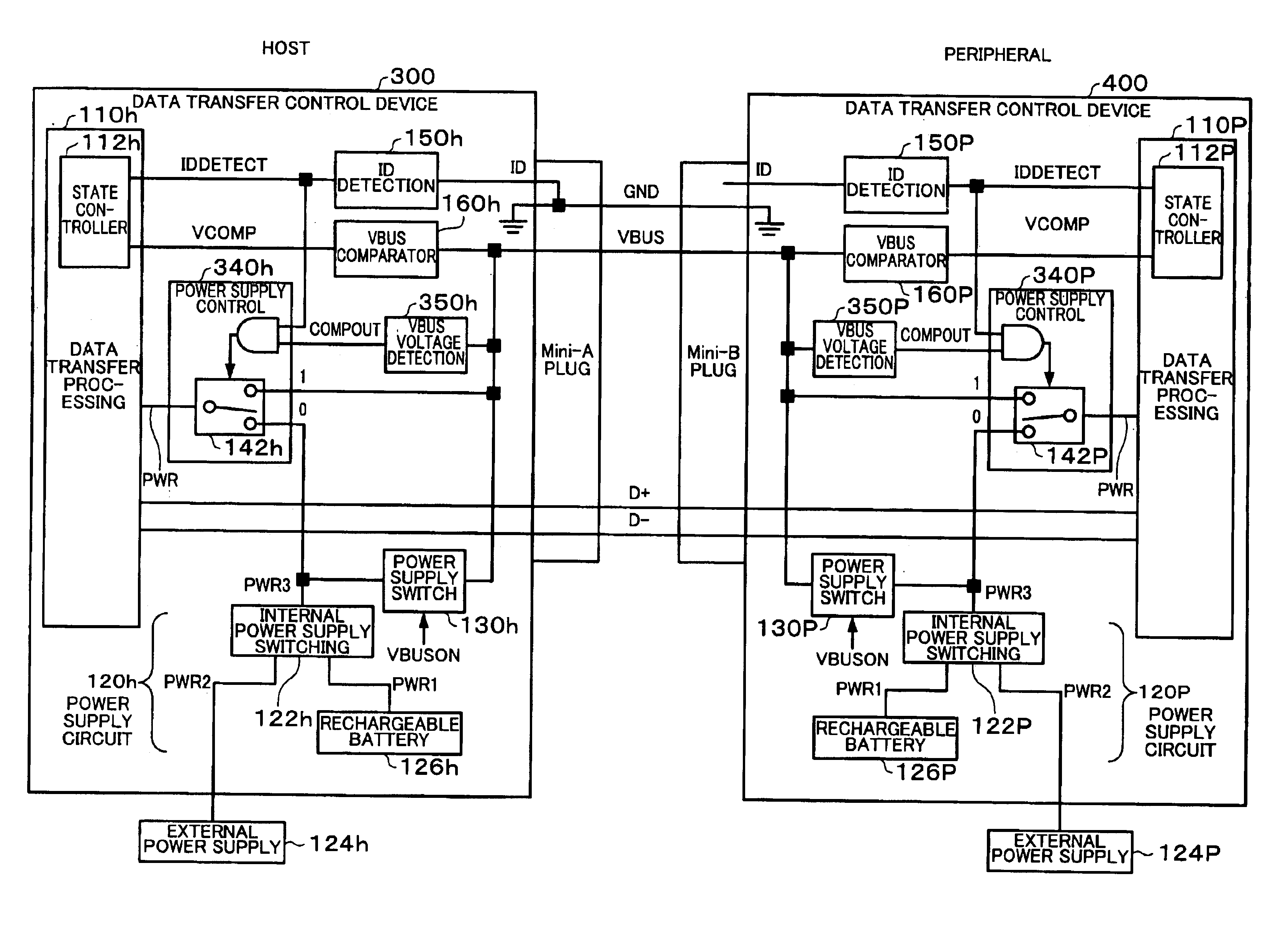
[0183]The first embodiment provides a data transfer control device capable of switching from the self-power supply to the bus power supply by using the power supply switching circuit 142 of the power supply control circuit 140. However, in the case where the connection partner which provides power to the VBUS line cannot provide power for some reason after switching to the bus power supply, the data transfer control device cannot but stop data transfer control as an abnormal state.

[0184]In a second embodiment, the internal circuits can continue operating normally by using a backup power supply even if the connection partner which provides power to the VBUS line stops providing power for some reason after switching to the bus power supply.

[0185]FIG. 9 shows an outline of a configuration of a data transfer control device in the second embodiment.

[0186]FIG. 9 shows a state in which data transfer control devices in the second embodiment are connected through a USB c...


PUM


Abstract

A state controller of a data transfer processing circuit switches an operation of an A-device or a B-device between a host operation and a peripheral operation by state transition. A power supply switch circuit connects a power supply circuit with a VBUS line based on transition of the state controller. A power supply switching circuit of a power supply control circuit connects the VBUS line or the power supply circuit with the data transfer processing circuit based on a switching signal. The switching signal is generated based on an output signal of a switch circuit or a control signal from the state controller.

Description

[0001]Japanese Patent Application No. 2002-253382 filed on Aug. 30, 2002, is hereby incorporated by reference in its entirety.BACKGROUND OF THE INVENTION[0002]The present invention relates to a data transfer control device, electronic equipment, and a power supply switching method.[0003]In recent years, the Universal Serial Bus (USB) standard has attracted attention as an interface standard for connecting a personal computer with a peripheral device (electronic equipment in a broad sense). However, data transfer according to the USB standard cannot be performed between peripheral devices without an intermediate host. Therefore, the “USB On-The-Go (OTG) 1.0” standard (hereinafter abbreviated as “OTG standard”) has been provided as a supplemental standard to the USB 2.0 standard, and has enabled data transfer according to the USB standard to be performed between peripheral devices.[0004]In the OTG standard, a peripheral which operates as a device in the USB standard is allowed to have...

Claims


Application Information

Patent Timeline
IPC IPC(8): G06F1/26G06F1/32G06F3/00G06F13/38
CPCG06F1/263G06F1/266
Inventor SAITO, NOBUYUKIOSHITA, SHUNNAGAO, KENYOU
Owner SEIKO EPSON CORP
Why Eureka
Try Eureka