Apparatus and technique for measuring permeability and permeant sorption

a technology of permeant sorption and apparatus, applied in the direction of fluid loss/gain rate measurement, fluid tightness measurement, instruments, etc., can solve the problems of higher water vapor loss, higher aroma loss, and inferior vapor barrier properties of plastic materials compared to glass and metal containers

Inactive Publication Date: 2005-11-15
TATA MURTHY
View PDF14 Cites 51 Cited by
  • Summary
  • Abstract
  • Description
  • Claims
  • Application Information

AI Technical Summary

Benefits of technology

[0016]Another object of the invention is to provide new and improved package

Problems solved by technology

However, plastic materials generally have inferior vapor barrier properties compared to glass and metal containers.
Accordingly, plastic packages generally admit oxygen into the package at a faster rate, show higher aroma loss, higher water vapor loss, and greater CO2 loss in case of carbonated beverage packages.
In addition, such small signal changes occur over very long periods of time (8 to 12 weeks—essentially the expected shelf life of the package) rendering these methods useless for rapid permeation assessment.
As such, these methods are of little predictive value.
Although loss rate methods are faster than the retained CO2 methods, they are often inaccurate and shelf life predictions from such methods often do not concur with measurements using the retained CO2 tests.
While in principle the method can also be applied to testing containers, such a configuration does not lend itself to nondestructive testing of whole containers.
Use of such a continuous purging system is also disadvantageous for other reasons.
Measuring such low concentrations of the permeants reliably is a challenge for most sensors.
In addition, the permeability of many barrier materials is highly sensitive to temperature and humidity conditions at the time of the test.
To my knowledge, the relevant prior art does not teach how testing at precisely controlled high relative humidities is to be conducted.
Precise control of humidity, especially

Method used


Image

  • Apparatus and technique for measuring permeability and permeant sorption
  • Apparatus and technique for measuring permeability and permeant sorption
  • Apparatus and technique for measuring permeability and permeant sorption

Examples


Embodiment Construction

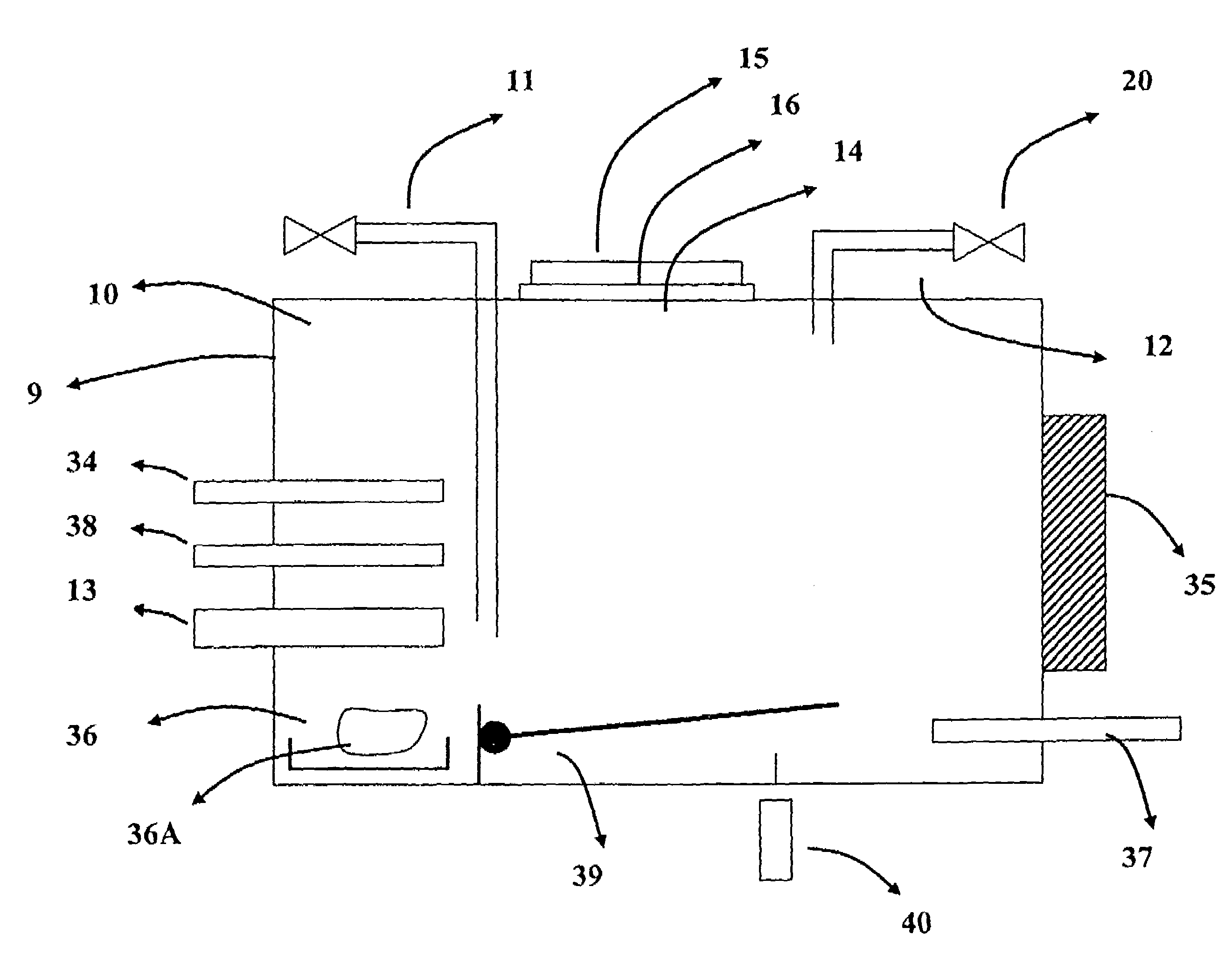
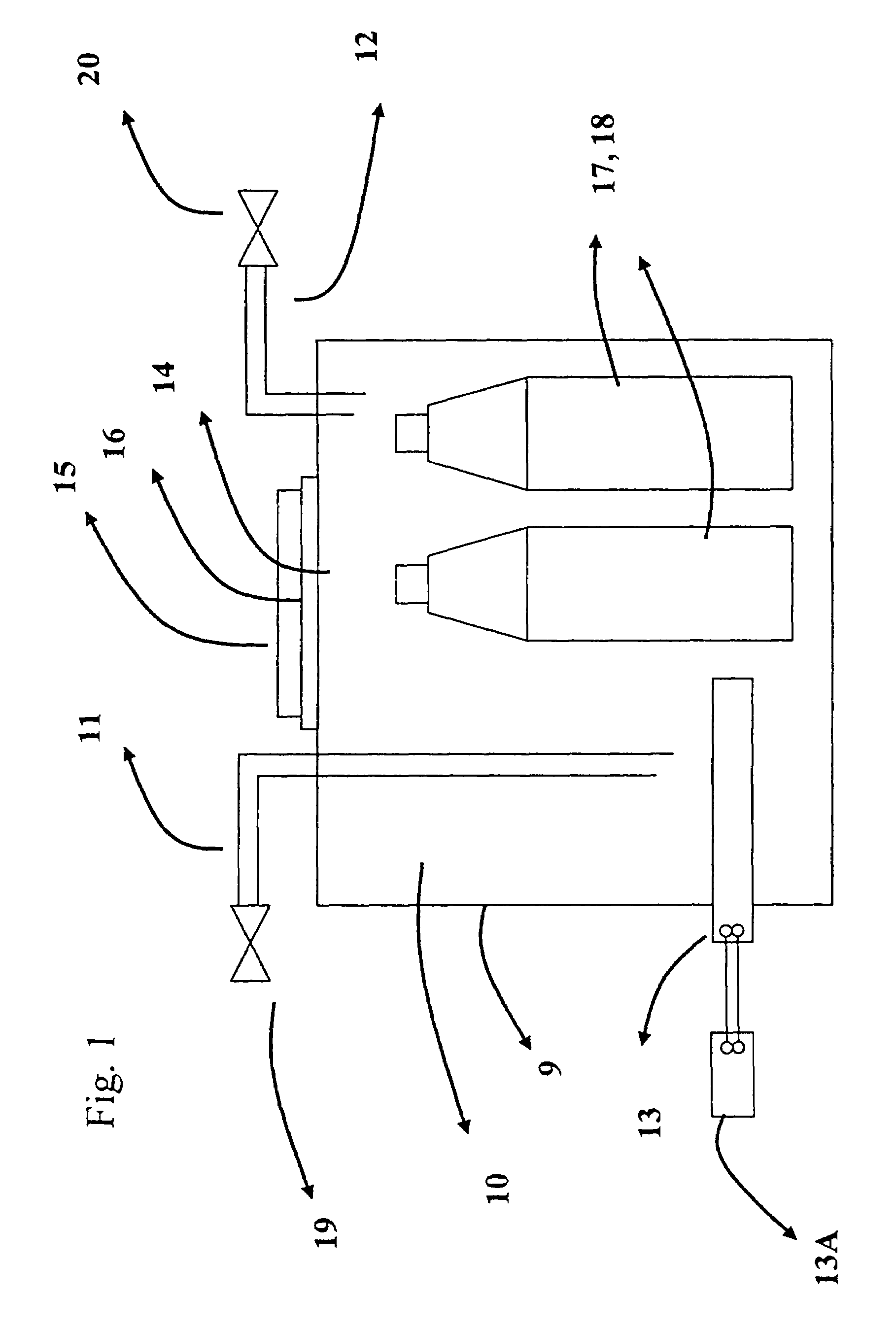
[0029]Turning now to the drawings in which like reference characters indicate corresponding elements, attention is first directed to FIG. 1 which illustrates a housing 9 defining an inner sealed chamber 10 with several attachments. Housing 9 and all the attachments are preferably made of materials substantially impervious to the permeant of interest, for example, stainless steel. Tubings 11 and 12, connected to an inlet and an outlet, respectively, of chamber 10, are used to flush chamber 10 with an inert medium. A valve 19 connected to tubing 11 and a valve 20 connected to tubing 12 are included for this purpose. A permeant sensor 13 is conveniently located at least partially within chamber 10 so that permeant within chamber 10 can be sensed and noted externally of chamber 10. The inert medium, which is also substantially free of the permeant, is chosen such that it does not interfere with the detection of permeant by permeant sensor 13.

[0030]For example, if carbon dioxide (CO2) is...


PUM


Abstract

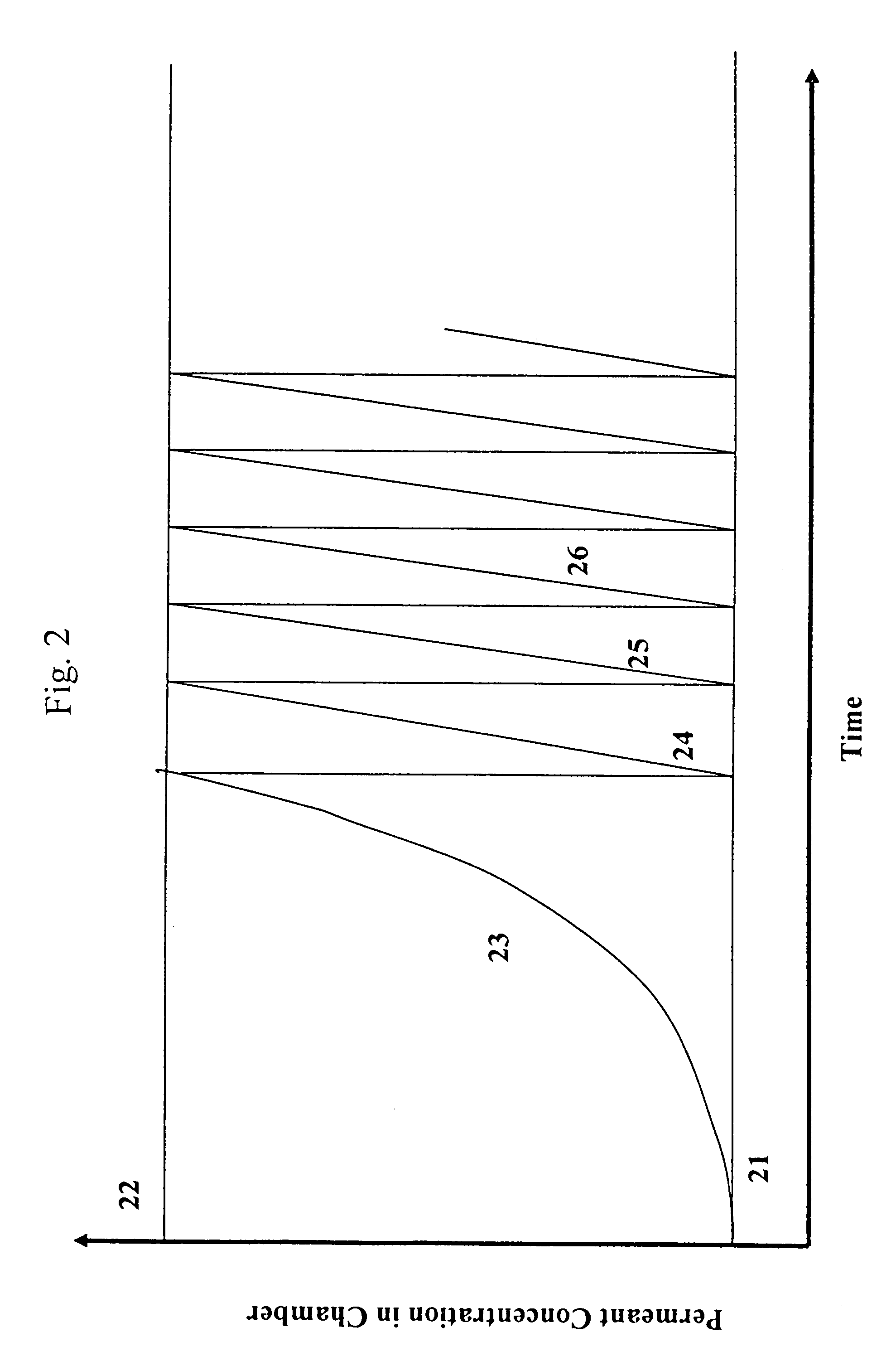
The invention is concerned with apparatus and methods for measuring package permeability and/or permeant sorption. The apparatus includes a housing defining an inner sealed chamber that is substantially impervious to a permeant of interest. The chamber has an inlet for introducing an inert medium substantially free of the permeant and an outlet for removing the inert medium. A sensor is positioned within the chamber and to provide signals indicative of permeant concentrations. A sealable opening is provided in the housing for introducing, within the chamber, packages to be measured for permeability and/or permeant sorption. In the method, testing of permeant concentrations is cycled to determine the slope of a time line between a low and a high concentration of the permeant. Humidity and temperature are preferably maintained constant within the chamber during testing.

Description

CROSS-REFERENCE TO RELATED APPLICATIONS[0001]This application claims the benefit of U.S. Provisional Application No. 60 / 418,444, filed 15 Oct. 2002.FIELD OF THE INVENTION[0002]The invention relates to measuring material permeability characteristics.[0003]More specifically, it relates to measuring gas or vapor diffusion through packaging materials.[0004]Even more specifically, it relates to measuring the flux of CO2 through bottles and films such as those used for packaging carbonated beverages.BACKGROUND OF THE INVENTION[0005]Plastics materials are increasingly being used in packaging applications, replacing glass and metal. However, plastic materials generally have inferior vapor barrier properties compared to glass and metal containers. Accordingly, plastic packages generally admit oxygen into the package at a faster rate, show higher aroma loss, higher water vapor loss, and greater CO2 loss in case of carbonated beverage packages. Other advantages afforded by plastics such as lig...

Claims


Application Information

Patent Timeline
IPC IPC(8): G01N15/08
CPCG01N15/082
Inventor TATA, MURTHY
Owner TATA MURTHY
Why Eureka
Try Eureka