
Antitheft design for rotary coin mechanisms

a technology of anti-thief design and coin disc rotation, which is applied in the direction of mechanical actuation, electric actuation, instruments, etc., can solve the problems of difficult task, unprofitable operation of vending machines or other service machines in areas without close supervision, etc., and achieve the effect of reducing the potential for a thief and extending the rotation amount of coin discs

Inactive Publication Date: 2005-11-15
NEW CONCEPT VENDING
View PDF21 Cites 5 Cited by
  • Summary
  • Abstract
  • Description
  • Claims
  • Application Information

AI Technical Summary

Benefits of technology

[0031]The present invention is directed to an apparatus that satisfies the need to prevent thieves from using a simple tool to defeat the rotary coin mechanism in order to receive product without proper payment.
[0033]The present invention is based on the recognition that the solution to this problem is not in preventing the insertion of a theft tool, but the prevention of the continued presence of the inserted theft tool as the rotary coin mechanisms rotates through past the coin detector. Thus, the solution is to force the removal of the inserted theft tool before the rotary coin mechanism rotates beyond the scrutiny of the coin detector.
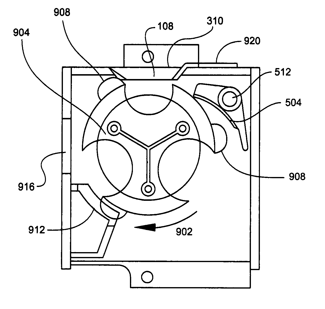
[0035]The present invention is an improved rotary coin mechanism with coin discs having tabs located near the trailing edges of the one or more coin slots present on each coin disc. The tabs shaped to prevent the continued presence of a theft tool in the casing of the rotary coin mechanism during the rotation of the relevant coin slot past the coin detector. The tabs are shaped so that the tab can pass by the coin detector. For retrofit applications, the tabs are sized so that they can be slid onto the stack of components without interference from the casing or other components. In one preferred embodiment, the leading edge of the coin detector casing is reinforced with an external brace to reduce the potential for a thief to distort the shape of the casing in an attempt to extend the amount of coin disc rotation before the theft tool must be removed.

Problems solved by technology

A coin mechanism that is easily defeated with readily available tools renders very expensive vending machines or other service machines unprofitable to operate in areas without close supervision.
This is a difficult task given the large amount of clearance available for tool insertion as an empty coin slot is rotated into the leading edge of the casing.

Method used


Image

  • Antitheft design for rotary coin mechanisms
  • Antitheft design for rotary coin mechanisms
  • Antitheft design for rotary coin mechanisms

Examples


Embodiment Construction

[0047]The present invention will now be described more fully hereinafter with reference to the accompanying drawings, in which preferred embodiments of the invention are shown.

[0048]This invention may, however, be embodied in many different forms and should not be construed as limited to the embodiments set forth herein; rather, these embodiments are provided so that this disclosure will be thorough and complete, and will fully convey the scope of the invention to those skilled in the art. Like numbers refer to like elements throughout.

[0049]The present invention thwarts the use of a tool to interfere with the operation of the detector detent through the use of one or more modifications. FIG. 9 shows the internals of the improved design from the top, left side, and from the front rather than from the rear. Arrow 902 shows the direction of rotation. In order to avoid undue clutter, elements of the rotary coin mechanism not required for the display of the solution to the theft problem...


PUM


Abstract

A method and apparatus for an improved rotary coin mechanism that prevents the theft of vending machine items by preventing the maintained presence of a theft tool used by a thief to interfere with the operation of a coin detector so that a coin slot without a coin of the prescribed size can be rotated past the coin detector to allow product to vend without the insertion of a coin of the prescribed size. The invention closes a gap between the rotating coin disc and the mechanism casing after a coin slot has entered into the rotary coin mechanism casing so that the theft tool cannot be maintained in an inserted position for a sufficient range of rotation of the rotary coin mechanism handle. The invention applies to rotary coin mechanisms that require one or more coins in order to obtain the vended item.

Description

[0001]This application claims priority to U.S. Provisional patent application No. 60 / 391,764 filed on Jun. 26, 2002 for Antitheft Design for Rotary Coin Mechanisms.[0002]In order to promote clarity in the description, common terminology for components is used. The use of a specific term for a component suitable for carrying out some purpose within the disclosed invention should be construed as including all technical equivalents which operate to achieve the same purpose, whether or not the internal operation of the named component and the alternative component use the same principles. The use of such specificity to provide clarity should not be misconstrued as limiting the scope of the disclosure to the named component unless the limitation is made explicit in the description or the claims that follow.BACKGROUND OF THE INVENTION[0003]1. Technical Field[0004]The present invention relates to coin mechanisms, particularly to those that are mechanical in nature, employing rotary coin re...

Claims


Application Information

Patent Timeline
IPC IPC(8): G07F1/02G07F1/00G07F1/04
CPCG07F1/02G07F1/041G07F1/047
Inventor SANTILLI, JR., RICHARD A.BEARD, GREG
Owner NEW CONCEPT VENDING
Learn More