Plastic lens system, compositions, and methods

a lens system and lens technology, applied in the field of eyeglass lenses, can solve the problems of lens yellowing, lens or mold cracking, optical distortion in the lens, etc., and achieve the effect of reducing the incidence of premature releas

Inactive Publication Date: 2005-11-15
VISION DYNAMICS
View PDF326 Cites 18 Cited by
  • Summary
  • Abstract
  • Description
  • Claims
  • Application Information

AI Technical Summary

Benefits of technology

[0017]An LCD panel for use as a filter is preferably a monochrome trans-flective panel with the back light and reflector removed. The intensity of the light is preferably reduced as the light passes through the LCD panel. The LCD panel is preferably programmable such that the light transmissibility of the LCD panel may be altered. In use, a predetermined pattern of light and dark regions may be displayed on the LCD panel to alter the intensity of light passing through the panel. One advantage of an LCD panel filter is that a pattern may be altered during a curing cycle. For example, the pattern of light and dark regions may be manipulated such that a lens is initially cured from the center of the lens, then the curing may be gradually expanded to the outer edges of the lens. This type of curing pattern may allow a more uniformly cured lens to be formed.
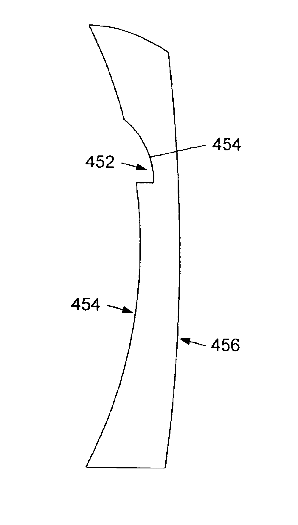
[0049]In another embodiment, a procedure for forming flat-top bifocal lenses is described. Flat-top bifocals include a far vision correction zone and a near vision correction region. The far vision correction zone is the portion of the lens which allows the user to see far away objects more clearly. The near vision correction zone is the region that allows the user to see nearby objects clearer. The near vision correction zone is characterized by a semicircular protrusion which extends out from the outer surface of an eyeglass lens. To reduce the incidence of premature release in flat-top bifocal lenses, it is preferred that polymerization of the lens forming composition in the front portion of the near vision correction zone is initiated before the portion of the lens forming composition in the far vision correction zone proximate the back mold member is substantially gelled. Preferably, this may be achieved by irradiating the front mold with activating light prior to irradiating the back mold with activating light. Alternatively, the incidence of premature release may also be reduced if the front portion of the near vision correction zone is gelled before gelation of the lens forming composition extends from the back mold member to the front mold member.

Problems solved by technology

Curing of a lens by ultraviolet light tends to present certain problems that must be overcome to produce a viable lens.
Such problems include yellowing of the lens, cracking of the lens or mold, optical distortions in the lens, and premature release of the lens from the mold.
In addition, many of the useful ultraviolet light-curable lens forming compositions exhibit certain characteristics that increase the difficulty of a lens curing process.
For example, due to the relatively rapid nature of ultraviolet light initiated reactions, it is a challenge to provide a composition that is ultraviolet light curable to form an eyeglass lens.
Excessive exothermic heat tends to cause defects in the cured lens.
While reducing the level of photoinitiator addresses some problems, it may also cause others.
For instance, lowered levels of photoinitiator may cause the material in regions near an edge of the lens and proximate a gasket wall in a mold cavity to incompletely cure due to the presence of oxygen in these regions (oxygen is believed to inhibit curing of many lens forming compositions or materials).
Uncured lens forming composition tends to result in lenses with “wet” edges covered by sticky uncured lens forming composition.
Furthermore, uncured lens forming composition may migrate to and contaminate the optical surfaces of the lens upon demolding.
The contaminated lens is then often unusable.
During such irradiation, however, higher than desirable levels of irradiation, or longer than desirable periods of irradiation, may be required.
The additional ultraviolet irradiation may in some circumstances cause defects such as yellowing in the lens.
The low photoinitiator levels utilized in many ultraviolet curable lens forming compositions may produce a lens that, while fully-cured as measured by percentage of remaining double bonds, may not possess sufficient cross-link density on the lens surface to provide desirable dye absorption characteristics during the tinting process.
An undesirable effect of this method, however, is that the lens tends to yellow as a result of such exposure.
Further, any contaminants on the surface of the lens that are exposed to short wavelengths of high intensity ultraviolet light may cause tint defects.
This method generally requires long exposure times and often the infrared radiation absorbed by the lens mold assembly will cause premature release of the lens from a mold member.
This method, however, is also associated with a higher rate of premature release.

Method used


Image

  • Plastic lens system, compositions, and methods
  • Plastic lens system, compositions, and methods
  • Plastic lens system, compositions, and methods

Examples


specific examples

[0479]The following examples are included to demonstrate embodiments of the invention. Those of skill in the art, in light of the present disclosure, should appreciate that many changes may be made in the specific examples that are disclosed and still obtain a like or similar result without departing from the spirit and scope of the invention.

example 1

Formation of a Plastic Lens by Curing with Activating Light

[0480]

Formulation:17%Bisphenol A bis(allyl carbonate)10%1,6 Hexanediol dimethacrylate20%Trimethylolpropane triacrylate21%Tetraethyleneglycol diacrylate32%Tripropyleneglycol diacrylate0.012%1 Hydroxycyclohexyl phenyl ketone0.048Methyl benzoylformateHydroquinone & Methylethylhydroquinone

Hydroquinone and Methylethylhydroquinone were stabilizers present in some of the diacrylate and / or triacrylate compounds obtained from Sartomer. Preferably the amount of stabilizers is minimized since the stabilizers affect the rate and amount of curing. If larger amounts of stabilizers are added, then generally larger amounts of photoinitiators must also be added.[0481]Light Condition: mW / cm2 measured at plane of sample with Spectroline DM 365N Meter from Spectronics Corp. (Westbury, N.Y.)

[0482]

CenterEdgeTop:0.2330.299Bottom:0.2170.248[0483]Air Flow: 9.6 standard cubic feet per minute (“CFM”) per manifold −19.2 CFM total on sample[048...

example 2

Oxygen Barrier Example #1

[0491]A liquid lens forming composition was initially cured as in a process and apparatus similar to that specified in Example 1. The composition was substantially the same as specified in Example 1, with the exception that hydroquinone was absent, the concentration of methylethylhydroquinone was about 25-45 ppm, the concentration of 1-hydroxycyclohexyl phenyl ketone was 0.017 percent, and the concentration of methylbenzoylformate was 0.068 percent. The composition underwent the initial 15 minute cure under the “1st activating light.” The apparatus was substantially the same as described for the above Example 1, with the following exceptions:[0492]1. The air flowrate on each side of the lens mold assembly was estimated to be about 18-20 cubic feet per minute.[0493]2. The air flowrate in and out of the chamber surrounding the lights was varied in accordance with the surface temperature of the lights. The air flowrate was varied in an effort to keep the temper...


PUM

PropertyMeasurementUnit
heataaaaaaaaaa
timeaaaaaaaaaa
abrasion resistantaaaaaaaaaa

Abstract

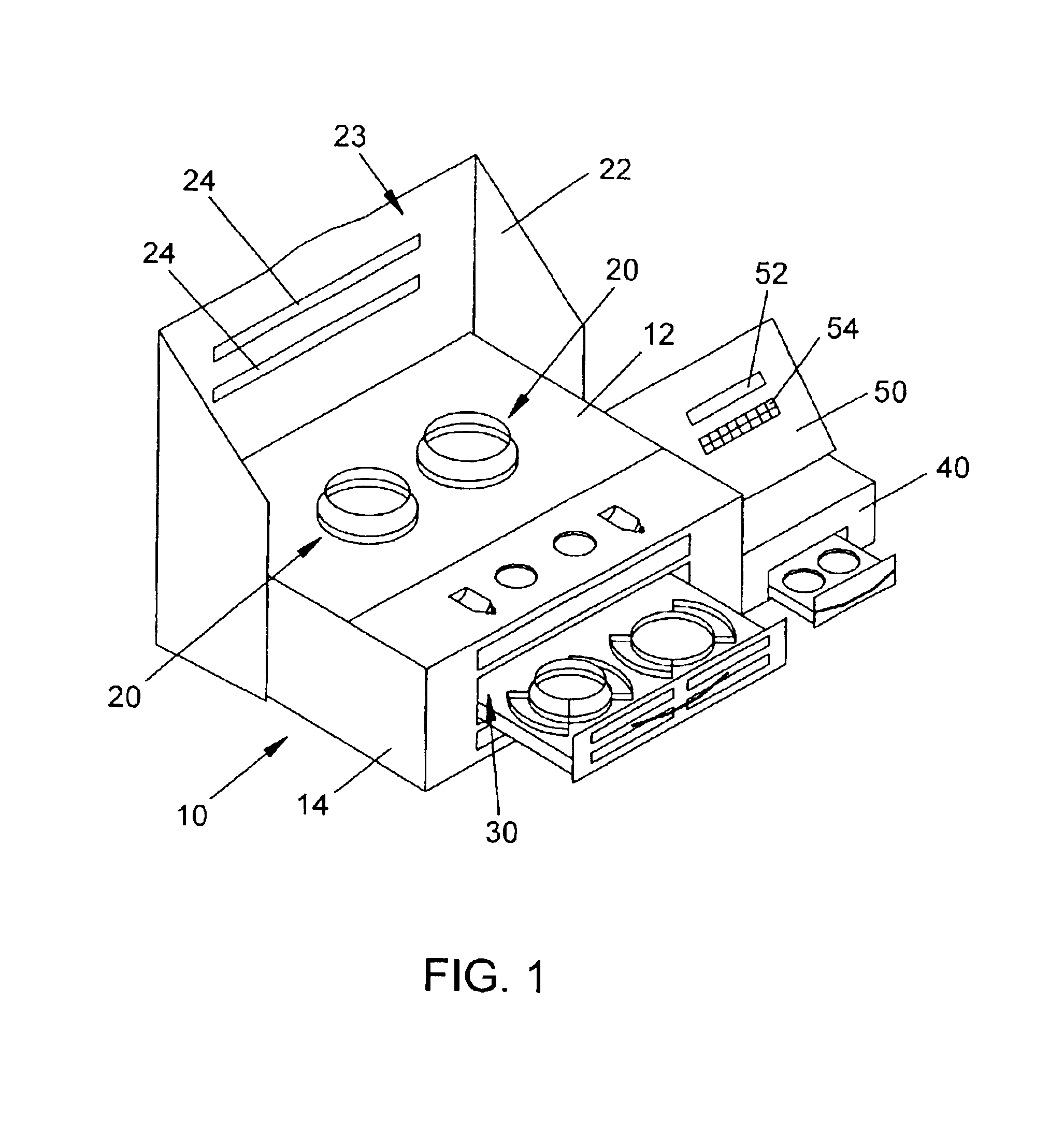
An apparatus for preparing a plastic eyeglass lens includes a coating unit and a lens curing unit. The apparatus is preferably configured to allow the operation of both the coating unit and the lens curing unit. The apparatus may also include a post-cure unit and a controller. The controller is configured to control the operation of the coating unit, the lens curing unit and the post-cure unit. A lens forming composition may include an aromatic containing polyether polyethylenic functional monomer, a photoinitiator, and a coinitiator. The lens forming composition may be cured by the application of activating light or activating light and heat.

Description

[0001]This application is a continuation of U.S. patent application Ser. No. 09 / 780,788 entitled “Plastic Lens Systems, Compositions, and Methods,” filed on Feb. 9, 2001, U.S. Pat. No. 6,634,879 which is a continuation application of U.S. patent application Ser. No. 09 / 272,815 entitled “Plastic Lens Systems, Compositions, and Methods,” filed on Mar. 19, 1999, now U.S. Pat. No. 6,419,873.BACKGROUND OF THE INVENTION[0002]1. Field of the Invention[0003]The present invention relates generally to eyeglass lenses. More particularly, the invention relates to a lens forming composition, system and method for making photochromic, ultraviolet / visible light absorbing, and colored plastic lenses by curing the lens forming composition using activating light.[0004]2. Description of the Relevant Art[0005]It is conventional in the art to produce optical lenses by thermal curing techniques from the polymer of diethylene glycol bis(allyl)-carbonate (DEG-BAC). In addition, optical lenses may also be m...

Claims


Application Information

Patent Timeline
Patent Type & Authority Patents(United States)
IPC IPC(8): B29D11/00G02B1/04C08F2/50
CPCB29D11/00442G02B1/041G02B1/043Y10T428/10Y10S425/808C09K2323/00B29C35/0888B29C35/0805B29C2035/0827B29C2035/0833B29C37/005
Inventor BUAZZA, OMAR M.LUETKE, STEPHEN C.POWERS, GALEN R.LATTIS, MATTHEW C.JOEL, LARRY H.
Owner VISION DYNAMICS
Why Eureka
Try Eureka