Endoscopic forceps instrument

a technology of endoscopic forceps and forceps, which is applied in the field of endoscopic forceps instruments, can solve the problems of relative low mechanical strength

Active Publication Date: 2005-11-15
HOYA CORP
View PDF15 Cites 430 Cited by
  • Summary
  • Abstract
  • Description
  • Claims
  • Application Information

AI Technical Summary

Benefits of technology

[0007]The invention is advantageous in that an instrume

Problems solved by technology

Further, the pair of rivet members is arranged such that the engaging portions thereof, which may be swaged or screw co

Method used


Image

  • Endoscopic forceps instrument
  • Endoscopic forceps instrument
  • Endoscopic forceps instrument

Examples


Embodiment Construction

[0023]Hereinafter, an embodiment of the invention will be described with reference to the accompanying drawings.

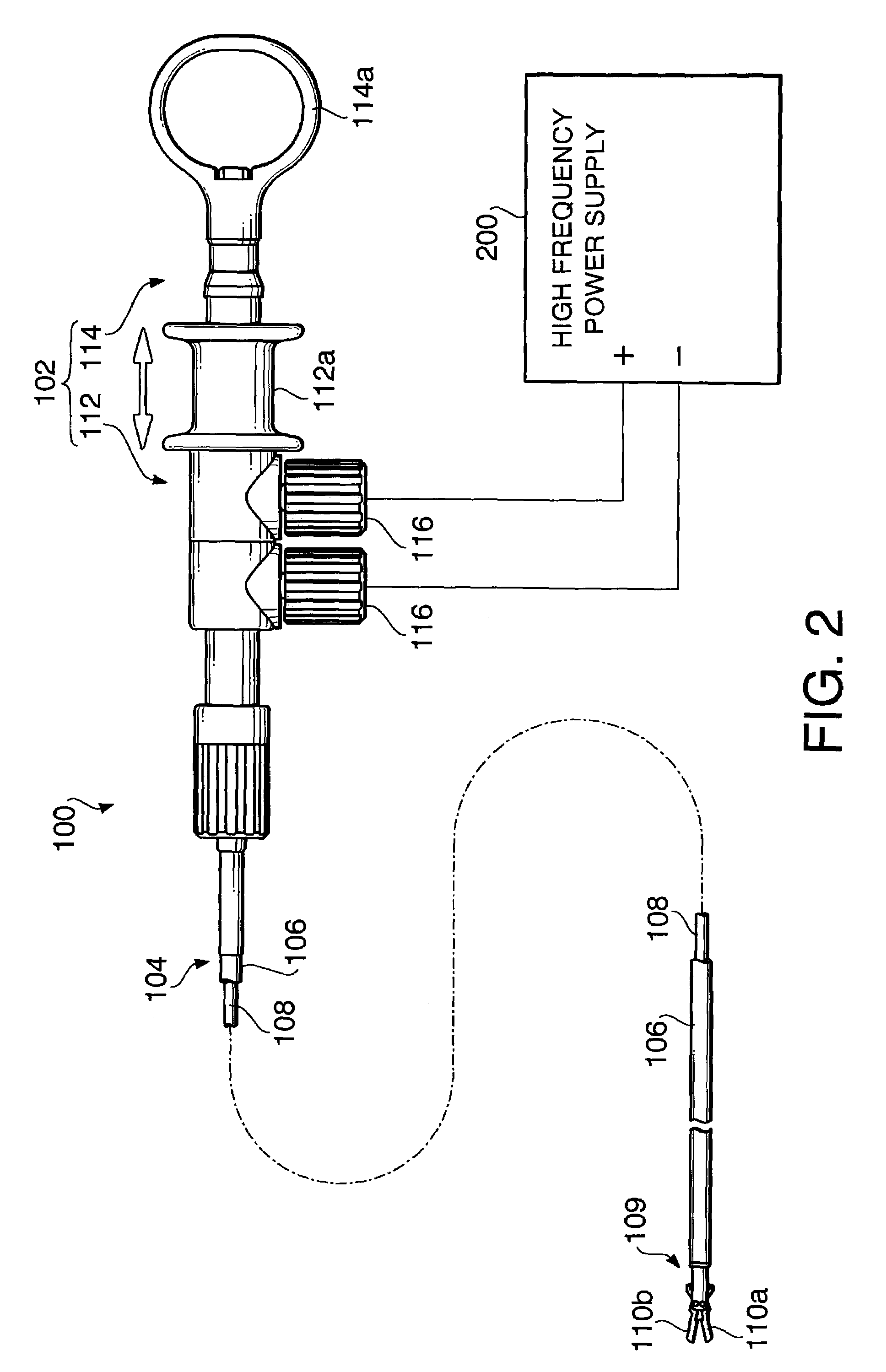
[0024]FIG. 2 schematically shows an endoscopic forceps instrument 100 according to an embodiment of the invention connected to a high frequency power supply 200.

[0025]The forceps instrument 100 includes an operation portion 102 and an inserting portion 104 connected to the distal end of the operation portion 102.

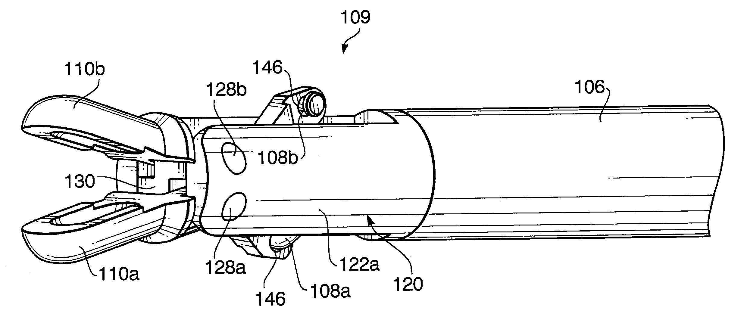
[0026]The inserting portion 104 is provided in a form and size that allows it to be introduced into a body cavity through a treatment tool inserting channel of an endoscope (not shown). The inserting portion 104 includes an elongated, flexible sheath 106, and a pair of conductive wires 108 (only one is shown) slidably passed through the sheath 106. The sheath 106 is made of insulating material such as poly-tetra-fluoro-ethylene (PTFE). In an exemplary embodiment, the sheath 106 is 1 m to 2 m long and has an outer diameter of 2 mm to 3 mm.

[0027]A forceps jaw assembl...


PUM


Abstract

An endoscopic forceps instrument has an inserting portion to be inserted into a body cavity through an endoscope, a clevis, a pair of rivets, and a pair of opposing jaws. The clevis is coupled to a distal end of the inserting portion. The pair of rivets is coupled to the clevis. Each of the rivets has a tip end that is swaged in order to fix the rivet to the clevis. The pair of opposing jaws is pivotably coupled to respective rivets so as to be movable between an open position and a closed position. The pair of rivets is arranged in parallel to each other. Further, the pair of rivets is arranged such that the tip ends thereof, which are swaged and therefore having relatively low mechanical strength, are located and swaged at opposite sides of the clevis.

Description

BACKGROUND OF THE INVENTION[0001]The present invention relates to an endoscopic forceps instrument having a pair of opposed jaws at the distal end thereof.[0002]Typical endoscopic forceps instruments having a pair of opposed jaws include, for example, biopsy forceps, grasping forceps, and hemostatic forceps.[0003]FIG. 1 shows a distal end of a conventional endoscopic forceps instrument 10. The endoscopic forceps instrument 10 includes a clevis 12 coupled to the distal end of a flexible sheath 11. A pair of opposing jaws 14 is pivotably coupled to the distal end of the clevis 12 by a rivet 15. The rivet 15 is inserted into the bores 16 formed to the distal end of the clevis, and extends across the slit 13 of the clevis 12.[0004]A pair of control wires (not shown) are inserted through the sheath 11 and connected to the pair of jaws 14. The pair of opposed jaws 14 open and close if the pair of wires is operated back and forth along the sheath 11 from the proximal end of the endoscopic ...

Claims


Application Information

Patent Timeline
IPC IPC(8): A61B18/14A61B1/00A61B17/28G02B23/24A61B18/12
CPCA61B18/1442A61B18/1492
Inventor KIDOOKA, SATOSHI
Owner HOYA CORP
Why Eureka
Try Eureka