
Fuel cell fuel supply system and mobile body

Inactive Publication Date: 2005-11-15
TOYOTA JIDOSHA KK
View PDF17 Cites 36 Cited by
  • Summary
  • Abstract
  • Description
  • Claims
  • Application Information

AI Technical Summary

Benefits of technology

[0011]In the first fuel supply system for fuel cells, the first movable body, and the fuel supply control method of the present invention, when it is determined that the fuel cells are in the power generation state, the technique prohibits a start of the supply of either the fuel or the source material to the storage module. This arrangement desirably prevents supply of the fuel or the source material during power generation of the fuel cells and thus ensures the safety in power generation of the fuel cells as well as in supply of the fuel or the source material. Namely the fuel supply accompanied with connection of the storage module with the fuel supply device is not carried out simultaneously with power generation of the fuel cells. This ensures sufficient safety. The determination of whether or not the fuel cells are in the power generation state may be, for example, based on the actual power generation of the fuel cells or based on input of an instruction of starting operation of the fuel cells.
[0014]This arrangement effectively prevents a start of supply of either the fuel or the source material in response to the instruction of starting the operation of the fuel cells, even prior to a sufficient output of electric power from the fuel cells, thus enhancing the safety.
[0017]A start of the supply of the fuel or the source material is prohibited when the output voltage from the fuel cells is not less than the predetermined level, even in the case where it is determined that the fuel cells are not in the power generation state. This arrangement desirably enhances the safety. In the fuel cells, even when the supplies of the fuel gas and the oxidizing gas are stopped in response to input of an instruction of stopping the operation of the fuel cells, the electrochemical reactions proceed until consumption of the existing supplies of the gases in the fuel cells. While it is determined that the fuel cells are not in the power generation state, in response to input of the instruction of stopping the operation of the fuel cells, the arrangement prohibits the start of the supply of either the fuel or the source material during the progress of the electrochemical reactions. This effectively prevents fuel supply while an undesired output voltage is produced.
[0019]The arrangement effectively prevents the start of fuel supply when actuation of another energy source is not prohibited, that is, when there is a possibility that the movable body moves. This effectively enhances the safety in fuel supply.
[0025]In the second fuel supply system for fuel cells, the second movable body, and the operation control method of the present invention, when it is determined that the fuel or the source material is being supplied to the storage module, the technique prohibits a start of power generation in the fuel cells. This arrangement desirably prevents operation of the fuel cells during supply of the fuel or the source material and thus ensures the safety in supply of the fuel or the source material. Namely the fuel supply accompanied with connection of the storage module with the fuel supply device is not carried out simultaneously with power generation of the fuel cells. This ensures sufficient safety. The determination of whether or not the fuel or the source material is being supplied may be, for example, based on the actual supply of the fuel or the source material to the storage module or based on input of a predetermined instruction, which is to be given prior to the start of the supply of the fuel or the source material.
[0027]This arrangement effectively prevents movement of the movable body in the course of supply of either the fuel or the source material, thus enhancing the safety in fuel supply.

Problems solved by technology

The safety of fuel supply to a system with fuel cells has, however, not been discussed fully.

Method used


Image

  • Fuel cell fuel supply system and mobile body
  • Fuel cell fuel supply system and mobile body
  • Fuel cell fuel supply system and mobile body

Examples


Embodiment Construction

[0038]In order to clarify the construction and the functions of the present invention, one mode of carrying out the present invention is described below in the following sequence as a preferred embodiment:

1. General Construction of Electric Vehicle

2. Structure Related to Supply of Hydrogen

3. Control in Process of Hydrogen Supply

4. Another Construction of Electric Vehicle

(1) General Construction of Electric Vehicle

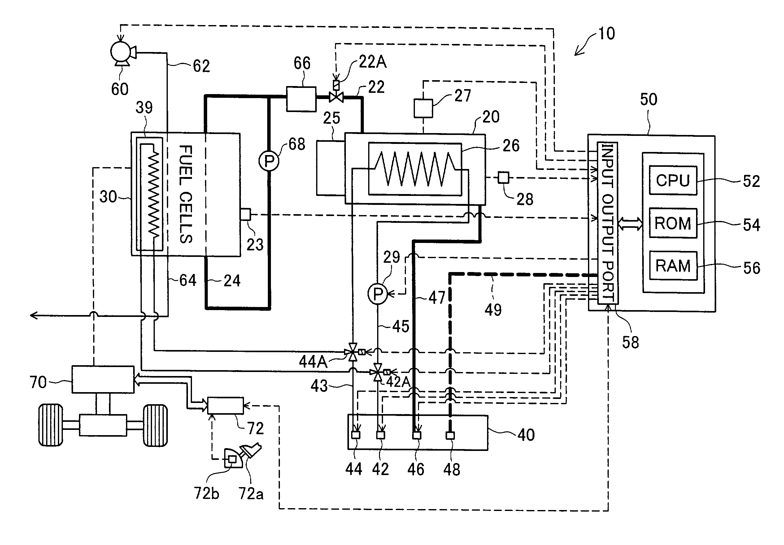
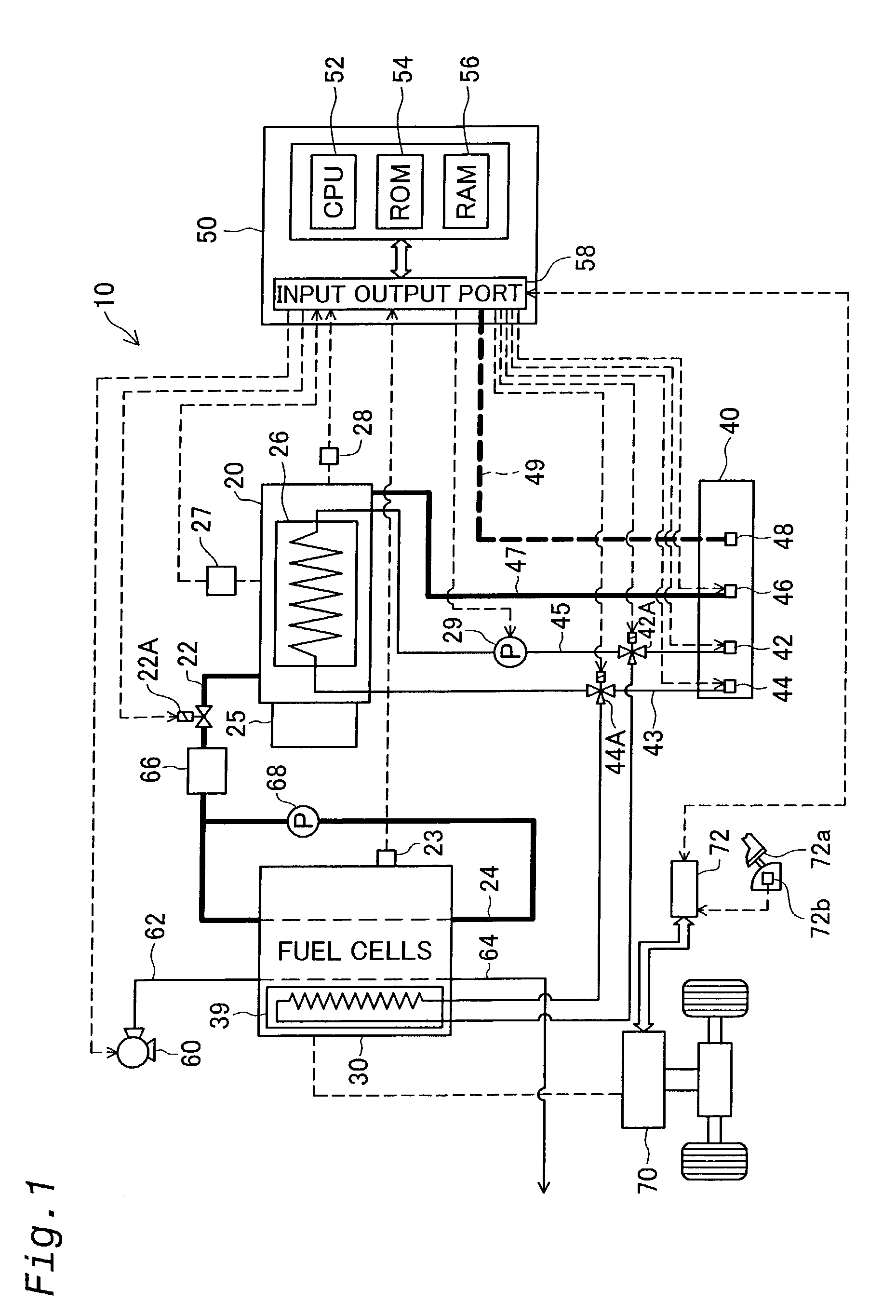
[0039]The construction of an electric vehicle is described first as one embodiment of the present invention. FIG. 1 illustrates the general construction of an electric vehicle 10 in one embodiment of the present invention. The electric vehicle 10 has a fuel tank 20, a stack of fuel cells 30, a connector receptor 40, and a controller 50, in addition to a predetermined vehicle structure including a motor 70. The following describes the respective constituents of the electric vehicle 10.

[0040]The fuel tank 20 stores externally supplied hydrogen gas, and feeds the hydrogen gas ...


PUM


Abstract

An electric vehicle with fuel cells mounted thereon has a fuel tank that stores a fuel therein, and a connector receptor that is connected to the fuel tank and is open to the surface of the vehicle body. A connector of a predetermined hydrogen supply device is fitted in and attached to the connector receptor, so that a supply of fuel is fed from the hydrogen supply device to the electric vehicle. The connector receptor is provided with a fuel lid for covering over the connector receptor. When it is determined that the fuel cells are in a working state, the fuel lid is not opened in response to input of an opening instruction of the fuel lid in the course of fuel supply. When it is determined that the fuel lid is open, on the other hand, operation of the fuel cells is not started in response to input of a starting instruction of the fuel cells in the electric vehicle. Such an arrangement enhances the safety of fuel supply to any system with fuel cells.

Description

TECHNICAL FIELD[0001]The present invention relates to a fuel supply system for fuel cells and a movable body. Specifically the present invention pertains to a fuel supply system for fuel cells, which functions to supply a fuel for the fuel cells or a source material used to generate the fuel for the fuel cells, as well as to a movable body.BACKGROUND ART[0002]A diversity of electric vehicles have been proposed, which utilize electrical energy output from fuel cells for the driving energy. Supply of a fuel, such as hydrogen, to the fuel cells is naturally required for power generation in the fuel cells. The electric vehicle of one known construction has hydrogen mounted thereon as the fuel for the fuel cells. The electric vehicle of another known construction has a source material, such as a hydrocarbon or a hydrocarbon compound, mounted thereon and reforms the source material to generate hydrogen gas and supply the hydrogen gas to the fuel cells.[0003]One proposed arrangement to mak...

Claims


Application Information

Patent Timeline
IPC IPC(8): B60L11/18B60K1/04B60L3/00B60K15/04B60K15/00H01M8/04C01B3/00H01M8/10
CPCB60K1/04B60K15/00B60K15/04B60L3/00B60L11/1885B60L11/1892B60L11/1894H01M8/04089H01M8/04201H01M8/04208H01M8/04223H01M8/04388H01M8/04425H01M8/04753H01M8/0494H01M8/04097H01M8/04559H01M2250/20Y02E60/324Y02T90/16Y02T90/32Y02T90/34Y02E60/50B60L58/31B60L58/33B60L58/34B60L58/40H01M8/0258H01M8/241H01M8/04225H01M8/04228H01M8/04302H01M8/04303H01M8/2457Y02E60/32Y02T10/70Y02T90/40H01M8/04H01M8/0267
Inventor HIRAKATA, SYUJI
Owner TOYOTA JIDOSHA KK
Learn More