Pressing device

a pressing device and pressing rod technology, applied in the direction of soldering apparatus, manufacturing tools,auxillary welding devices, etc., can solve the problems of difficult to delicately change the pressing force during high-speed welding and work, the pressing direction cannot be changed, and the pressing force cannot be controlled. , to achieve the effect of easy control of the position, speed and pressing force of the roller

Inactive Publication Date: 2005-11-15
FANUC LTD
View PDF8 Cites 20 Cited by
  • Summary
  • Abstract
  • Description
  • Claims
  • Application Information

AI Technical Summary

Benefits of technology

[0018]Since the pressing device in accordance with the present invention has the above-described configuration, the pressing operation of the roller of the pressing device is controlled by the servomotor. Therefore, the position, speed, and pressing force of the roller can be controlled easily, so that the optimum pressing force can be applied to the plate portion even for various types of workpieces.

Problems solved by technology

In the case where a coil spring is used to control the pressing force of the roller, the pressing force cannot be controlled, and various kinds of plate portions of workpieces with different shapes and plate thicknesses cannot be pressed by one type of pressing device.
In this case, however, there arises a problem in that the response is slow, so that it is difficult to delicately change the pressing force during high-speed welding and working.
Also, the conventional construction is such that only a damper is disposed so as to respond to variations in distance between the working tool such as a welding head and the plate portion, and the roller pressing direction cannot be changed when the angle of the working tool such as a welding head with respect to the plate portion changes.
Therefore, if the angle of the working tool such as a welding head with respect to the plate portion changes, the pressing force changes accordingly, which presents a problem in that high-quality working including welding cannot be performed.

Method used


Image

  • Pressing device
  • Pressing device
  • Pressing device

Examples


first embodiment

[0035]the present invention will be described with reference to FIGS. 1 and 2.

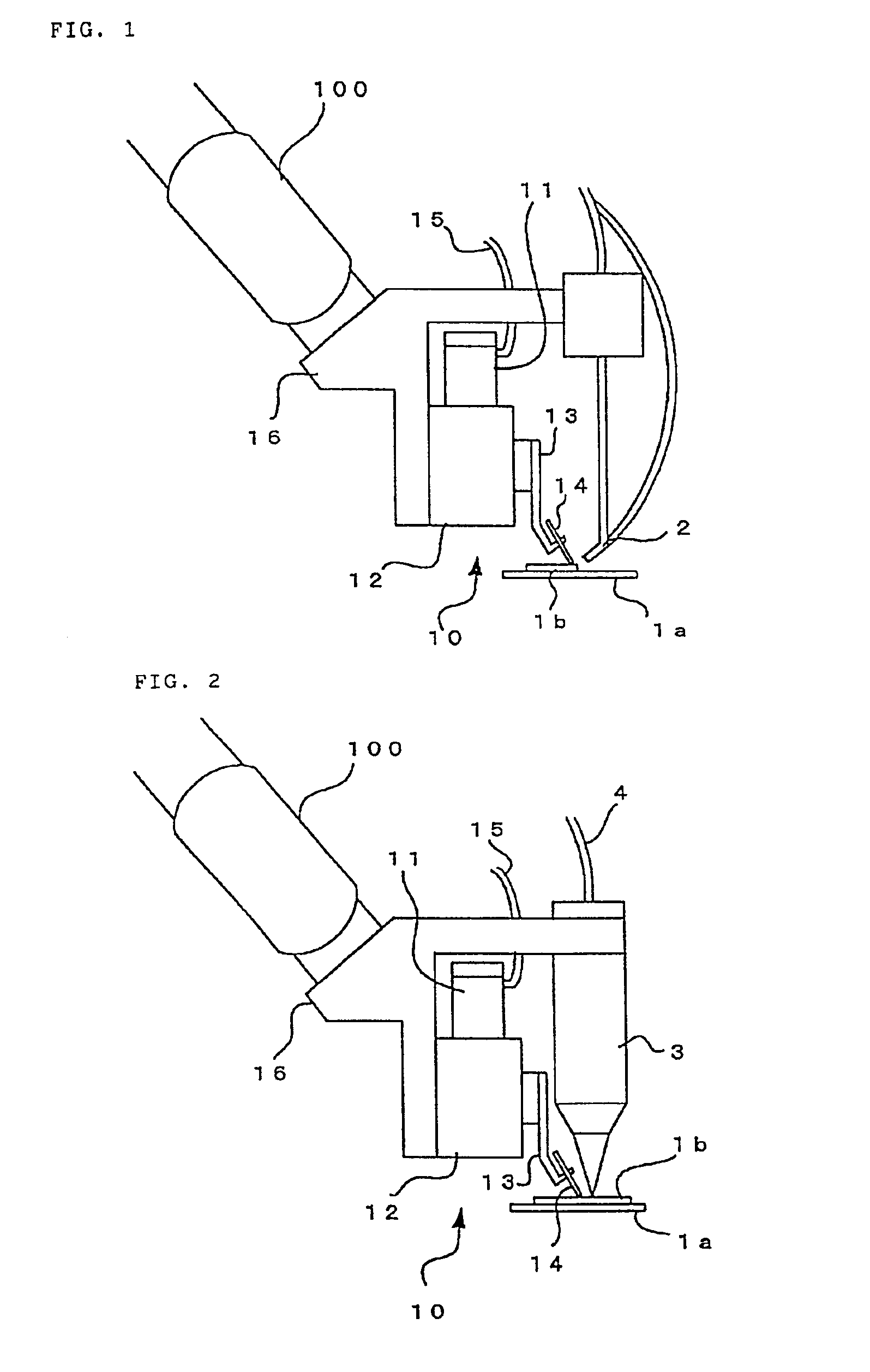
[0036]FIG. 1 shows an example of a pressing device applied to welding operation using a welding torch as a working tool.

[0037]In FIG. 1, a pressing device 10 is made up of a bracket 16, a servomotor 11, a linear movement mechanism 12 driven by the servomotor 11, a roller support frame 13 fixed to a moving member of the linear movement mechanism 12, and a roller 14 pivotally mounted at the distal end of the roller support frame 13. The configuration is such that the bracket 16 of the pressing device 10 is installed at the distal end of a robot arm 100, by which the pressing device 10 is mounted on the robot arm 100. Further, the bracket 16 has a working tool mounting section, and in the example shown in FIG. 1, a welding torch 2 is mounted to the working tool mounting section. In the figure, reference numeral 15 denotes a cable for the servomotor 11.

[0038]When the servomotor 11 is driven, the roller 14 can ...


PUM

PropertyMeasurementUnit
thicknessaaaaaaaaaa
speedaaaaaaaaaa
pressing forceaaaaaaaaaa

Abstract

A laser welding nozzle used as a working tool, a linear movement mechanism of a pressing device, and a servomotor are fixed to a bracket. A roller support frame is fixed on a moving side of the linear movement mechanism. A roller is pivotally mounted at a distal end of the roller support frame. The roller is located in the vicinity of a weld point of the laser welding nozzle. By driving the servomotor in a controlled manner, a portion in the vicinity of the weld point of a plate portion to be welded is pressed by the roller to restrain a floating of the weld portion, by which a gap between the plate portions is regulated, and thus uniform weld can be obtained. The pressing position, speed, and pressing force of roller can be controlled easily, so that the pressing device can be used for various types of workpieces.

Description

BACKGROUND OF THE INVENTION[0001]1. Field of the Invention[0002]The present invention relates to pressing means for pressing a plate portion at the time of working using various welding apparatuses or a laser beam machining apparatus, and an industrial robot.[0003]2. Description of the Prior Art[0004]When plate portions are welded, a gap between two lapped plate portions has an influence on the weld quality. Therefore, a method is known in which welding is performed while plate portions are pressed by a pressure roller or the like in order to correct the floating of plate portion so that the gap is kept constant.[0005]For example, Japanese Patent Application Laid-Open No. 8-90264 has discloses a method in which welding is performed while plate portions to be welded are pressed by a roller from the upside of the lap joint in laser welding. FIG. 14 shows a method for laser welding. In this method, a bracket 67 attached to the distal end of a robot arm 100 is provided with a laser weld...

Claims


Application Information

Patent Timeline
Patent Type & Authority Patents(United States)
IPC IPC(8): B23K26/00B23K26/02B23K26/24B23K37/04B23K9/025B23K9/12B23K26/10B23K26/21
CPCB23K26/243B23K26/246B23K26/023B23K26/037B23K26/242B23K26/244
Inventor TERADA, AKIHIROSUGIYAMA, HIDEKIMORIOKA, MASAHIRO
Owner FANUC LTD
Why Eureka
Try Eureka