Method and apparatus for testing synchronization circuitry

a synchronization circuit and circuit technology, applied in the field of methods and apparatus for testing synchronization circuitry, can solve the problems of frequency capture and lock range, limited lock range of analog plls used in tdm synchronization circuits, and limited practical design limitations of synchronization and timing recovery

Inactive Publication Date: 2005-11-15
CISCO TECH INC
View PDF8 Cites 23 Cited by
  • Summary
  • Abstract
  • Description
  • Claims
  • Application Information

AI Technical Summary

Benefits of technology

[0018]A phase locked loop synchronization circuit generates an output frequency locked to one of a selection of input reference frequencies, or to a fixed, accurate time base frequency. A test circuit uses the fixed, accurate time base frequency reference signal to generate an output frequency with controlled frequency offset as one of the...

Problems solved by technology

PLLs used for synchronization and timing recovery have practical design limitations.
One such limitation is frequency capture and lock range.
Good jitter performance, crystal base...

Method used


Image

  • Method and apparatus for testing synchronization circuitry
  • Method and apparatus for testing synchronization circuitry
  • Method and apparatus for testing synchronization circuitry

Examples


Embodiment Construction

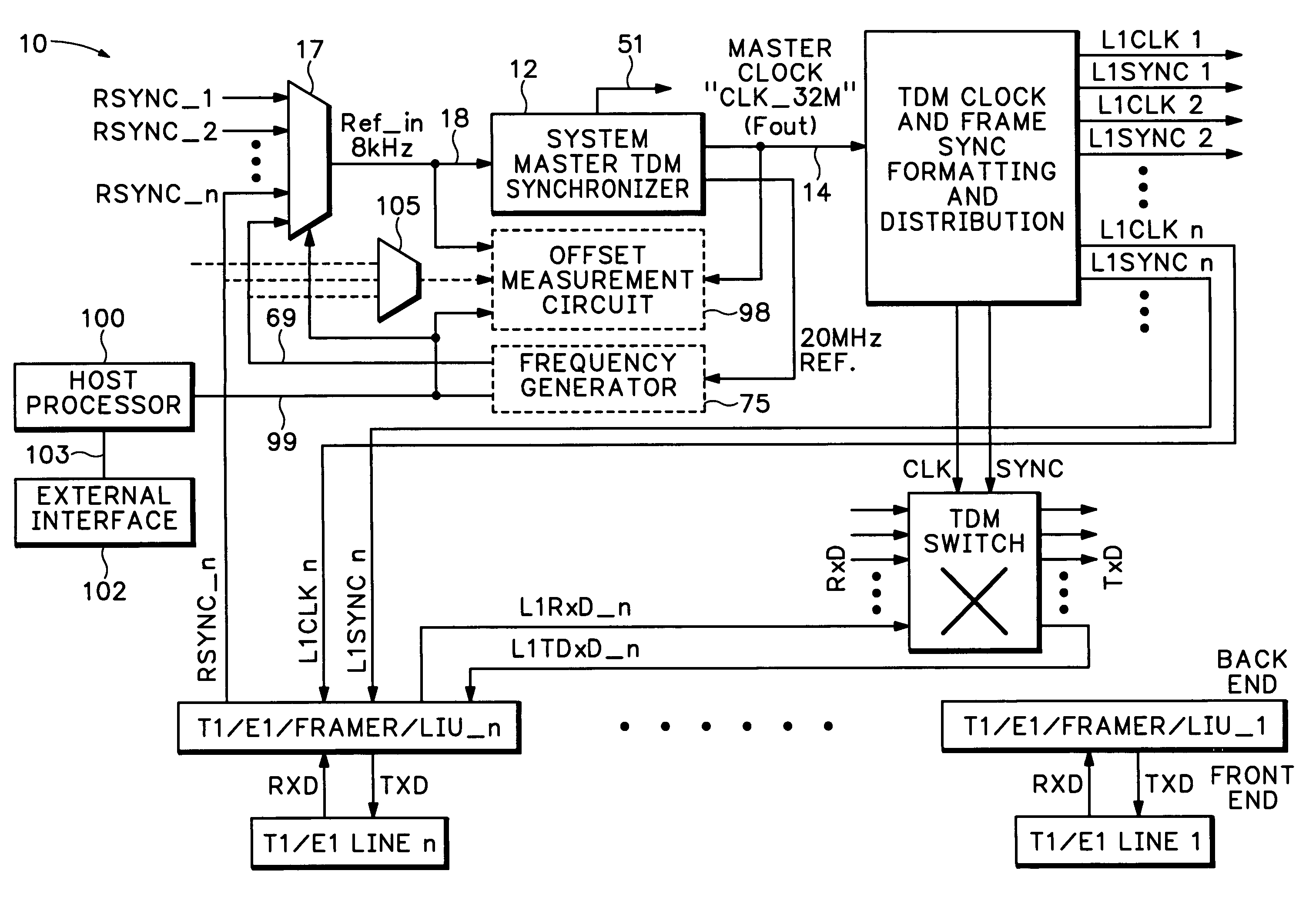
[0029]In order to confirm that the APLL 54 and the DPLL 50 together are capable of locking to the required range of input frequencies, a frequency synthesis scheme using dithering techniques is employed to produce an 8 kHz+ / −“offset” ppm frequency at the input to the DPLL 50 (FIG. 3).

[0030]A suitably chosen low frequency (Flow) and high frequency (Fhigh) are used to synthesize the input reference frequency (Ref—in). To confirm that the APLL and DPLL are locked, a frequency counter clocked from Fout (32.768 MHz) of APLL 54 measures the number of counts over an integral number N of Ref—in 18 periods. When locked, the resulting count should be N*32768 / 8=N*4096. Any deviation from this count represents a “ppm” difference of output Fout—APLL 14 relative to the input frequency Ref—in 18.

[0031]The same integration frequency counter can be used to measure the absolute deviation of an external 8 kHz RSYNC signal relative to the accurate / stable 20 MHz signal. In one embodiment, the 32.768 MHz...


PUM


Abstract

A test circuit receives a reference signal having a reference frequency and generates a synchronizer input signal having a synchronizer input frequency for inputting into a synchronizer circuit. A frequency generator is configured to offset the synchronizer input frequency at selectable frequencies from a nominal frequency value. An offset measurement circuit is configured to compare the frequency offset for the synchronizer input frequency with the frequency offset of a synchronizer output signal.

Description

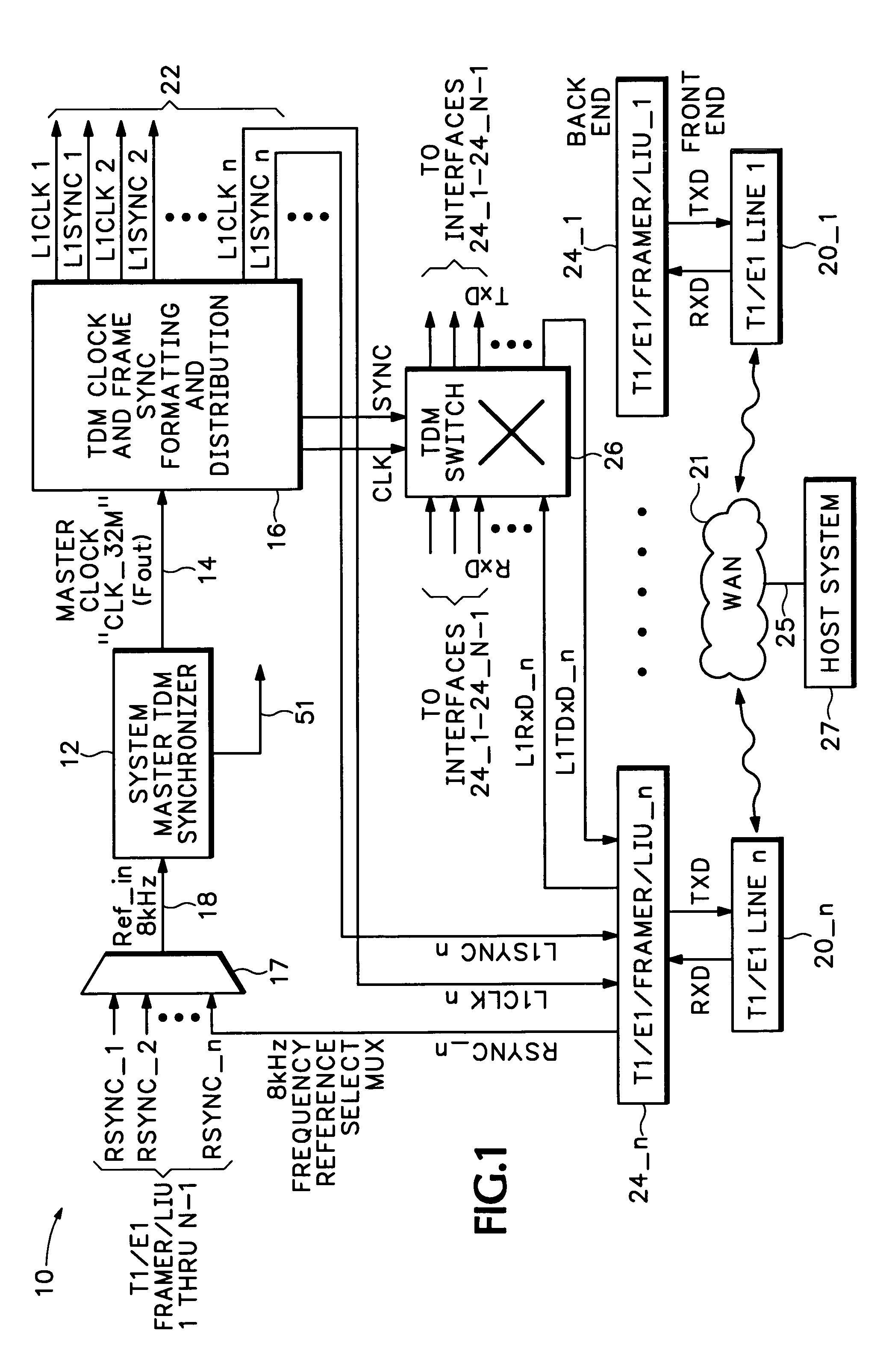
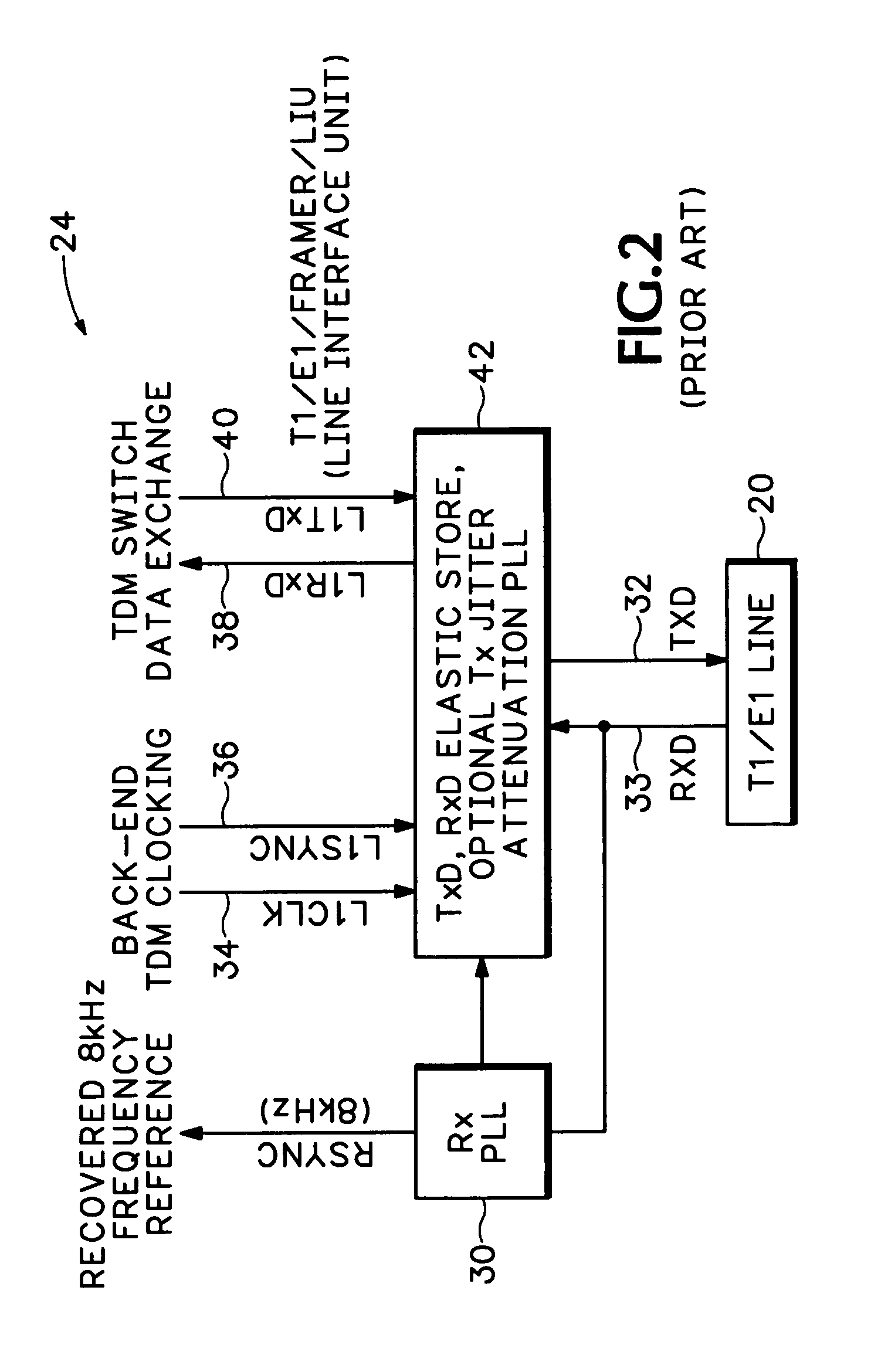
BACKGROUND[0001]A communications system such as a multi-service router may employ one or more synchronous interfaces such as T1 or E1 interfaces. It is often desirable to exchange data received on one interface with another interface for transfer to an external communications system. In order to make different communication systems synchronous, it may be necessary to transfer clocking information from one communications system to one or more different communications systems using these interfaces. Synchronous data transfer without data loss requires such systems to be synchronized.[0002]Synchronous interfaces may transfer clocking information embedded / encoded in the data itself. Alternatively, synchronous interfaces may use a separate medium to transfer clocking, other than the medium used to transfer data. Examples of such synchronous serial interfaces include those defined by the Electronic Industries Association EIA-530 and EIA-449 standards.[0003]A T1 or E1 interface embeds cloc...

Claims


Application Information

Patent Timeline
IPC IPC(8): G01R23/00G01R23/12H03L7/06H04J3/06H04J3/14H04L1/24
CPCH04J3/14H04L1/24H04J3/0688
Inventor HEY, GEORGE MICHAEL
Owner CISCO TECH INC
Why Eureka
Try Eureka