
Queue-based spin lock with timeout

a timeout and spin lock technology, applied in the field of spin locks, can solve the problems of inability to guarantee that space will be reclaimed in bounded time in multi-programmed systems, timeout may be indefinitely delayed on a multi-programmed system, and space may not be reclaimed

Inactive Publication Date: 2005-11-15
UNIVERSITY OF ROCHESTER
View PDF4 Cites 67 Cited by
  • Summary
  • Abstract
  • Description
  • Claims
  • Application Information

AI Technical Summary

Benefits of technology

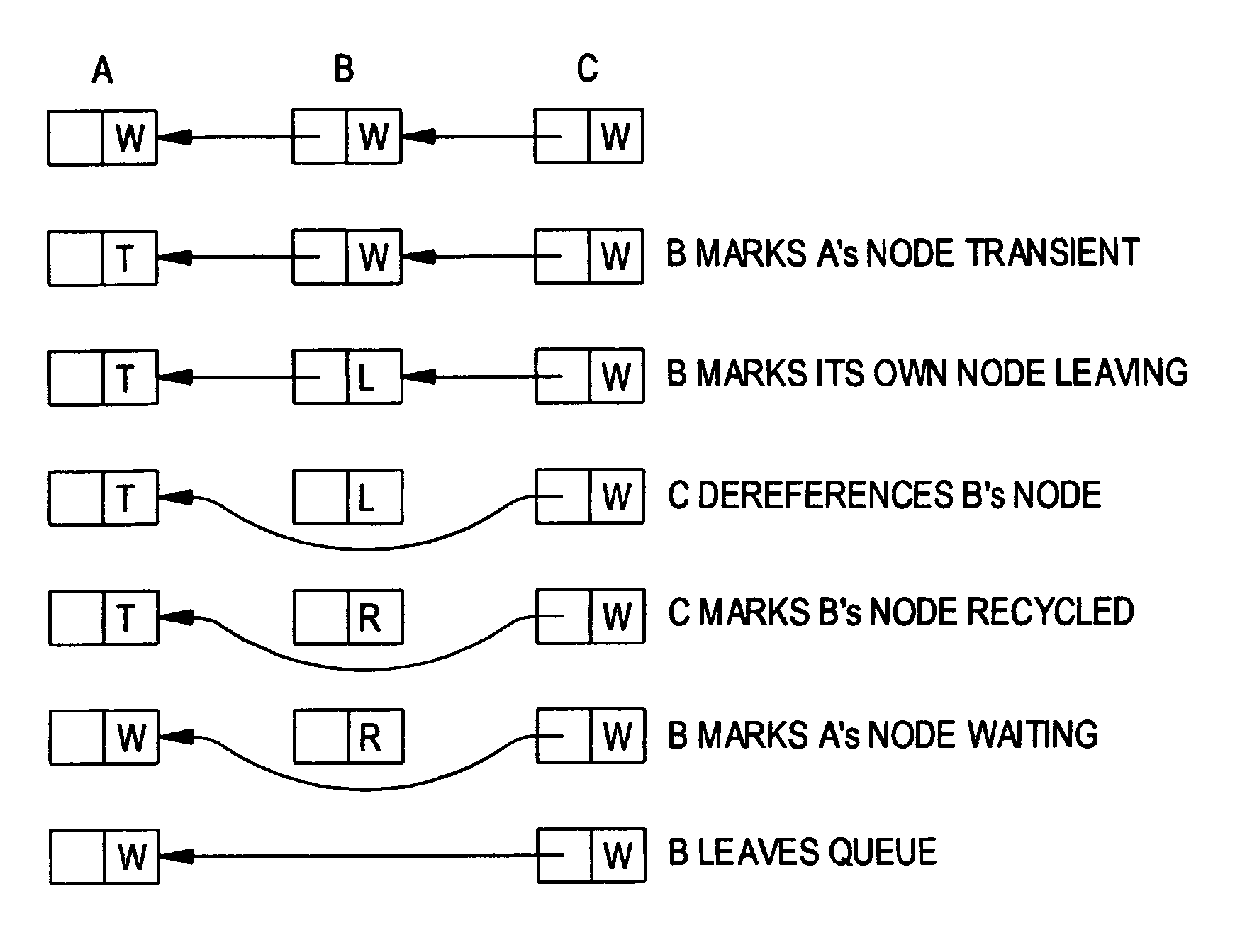
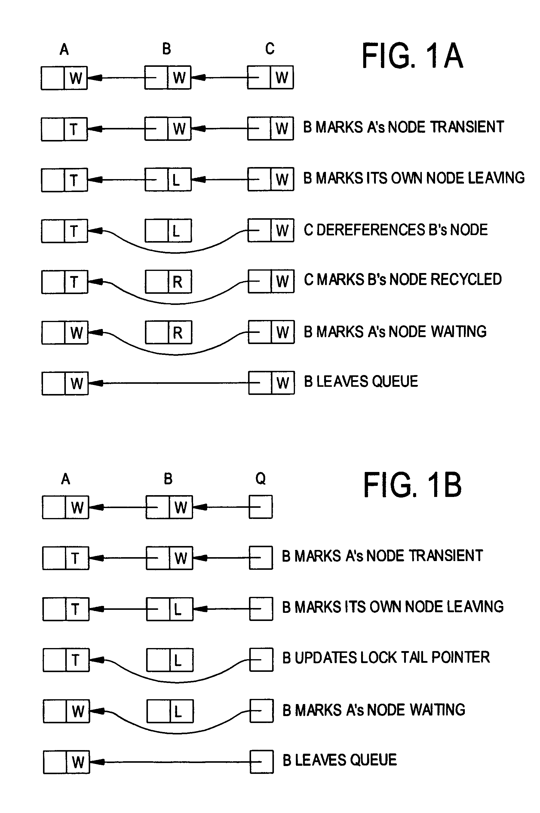
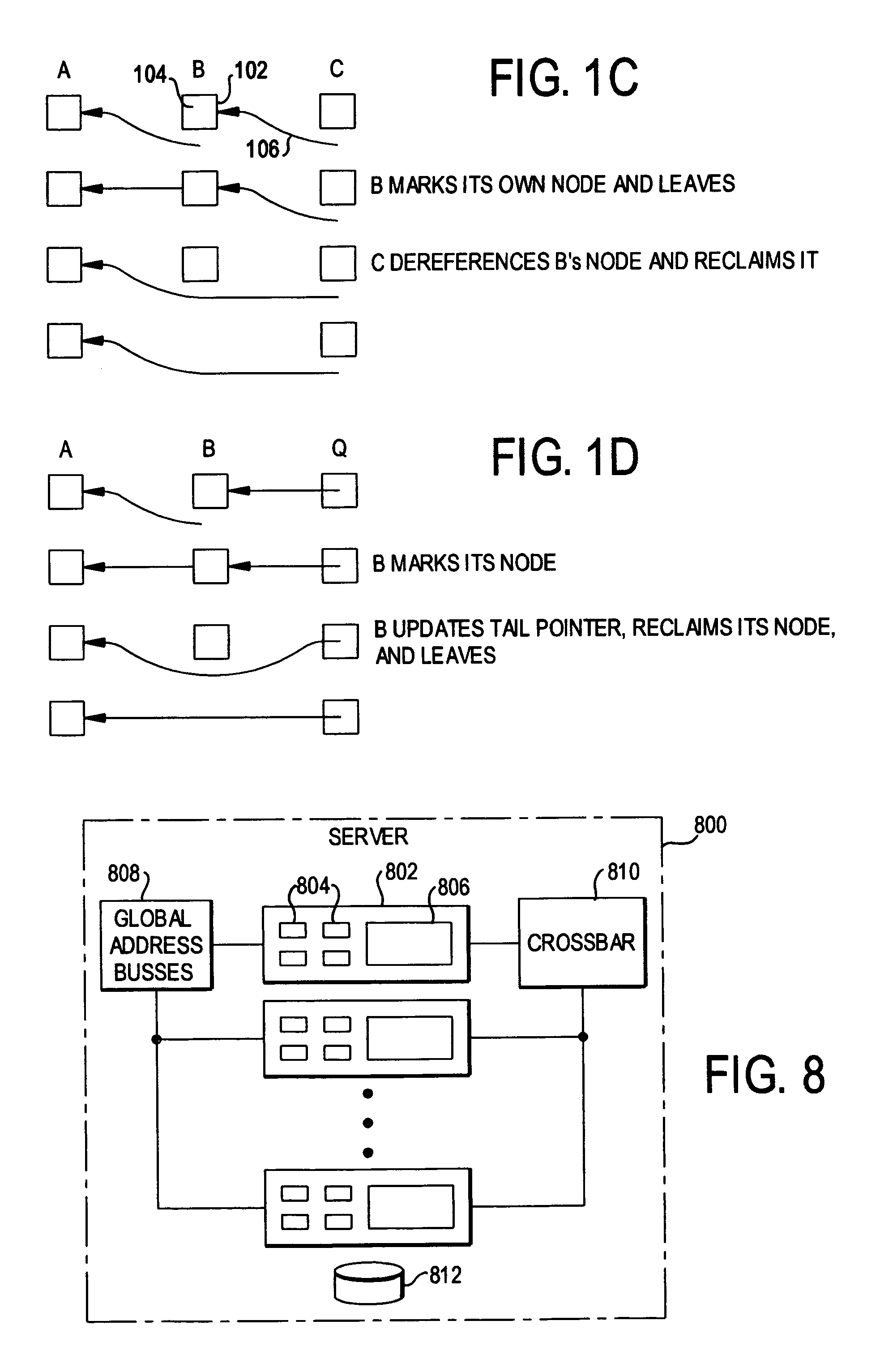
[0018]Two preferred embodiments of each lock variant will be disclosed, one based on the CLH lock and the other on the MCS lock. The variants with guaranteed linear space but blocking timeout are herein named the CLH try lock and the MCS try lock. The variants with non-blocking timeout are herein named the CLH-NB try lock and the MCS-NB try lock. In each pair the CLH embodiment is the simpler of the two, but relies on cache coherence. The MCS embodiments can be expected to scale better on non-cache-coherent machines.

Problems solved by technology

Unfortunately, it does not appear to be possible to guarantee that space will be reclaimed in bounded time in multiprogrammed systems.
Space needs are therefore linear (O(L+T)), but timeout may be indefinitely delayed on a multiprogrammed system, because a neighbor thread may be preempted, and thus unable to cooperate.
Space, however, may not be reclaimed until some successor is active.

Method used


Image

  • Queue-based spin lock with timeout
  • Queue-based spin lock with timeout
  • Queue-based spin lock with timeout

Examples


Embodiment Construction

[0046]Two preferred embodiments of the invention will now be set forth in detail with reference to the drawings. Two variants of each embodiment are described: one with guaranteed linear space but blocking timeout, the other with non-blocking timeout but theoretically unbounded space.

[0047]The first preferred embodiment (variant with blocking timeout) is called the CLH try lock. It is based on the earlier CLH lock of Craig (“Building FIFO and priority-queueing spin locks from atomic swap,” Technical Report TR 93-02-02, Department of Computer Science, University of Washington, February, 1993) and of Landin and Hagersten (“Queue locks on cache coherent microprocessors,” 8th Intl. Parallel Processing Symposium, Cancun, Mexico, April, 1994, pp. 165–171).

[0048]In the standard CLH lock, a thread leaves its queue node behind when releasing the lock. In its place, it takes the node abandoned by its predecessor. For a try lock, one would like to arrange for a thread that times out to leave w...


PUM


Abstract

A queue-based spin lock with timeout allows a thread to obtain contention-free mutual exclusion in fair, FIFO order, or to abandon its attempt and time out. A thread may handshake with other threads to reclaim its queue node immediately (in the absence of preemption), or mark its queue node to allow reclamation by a successor thread.

Description

REFERENCE TO RELATED APPLICATION[0001]The present application claims the benefit of U.S. Provisional Application No. 60 / 361,063, filed Mar. 1, 2002, whose disclosure is hereby incorporated by reference in its entirety into the present disclosure.STATEMENT OF GOVERNMENT INTEREST[0002]The work leading to the present invention was supported in part by NSF grants EIA-0080124, CCR-9988361 and CCR-0204344 and by DARPA / AFRL contract number F29601-00-K-0182. The government has certain rights in the invention.FIELD OF THE INVENTION[0003]The present invention is directed to a spin lock for use on shared-memory multi-processor computing devices and more particularly to a queue-based spin lock with timeout.DESCRIPTION OF RELATED ART[0004]Large-scale databases and Internet transaction applications now demand parallel servers capable of running on machines with twenty to a hundred processors or more. On such machines, spin locks are widely used for mutual exclusion. Traditional test—and—set-based...

Claims


Application Information

Patent Timeline
IPC IPC(8): G06F12/00G06F9/46
CPCG06F9/52
Inventor SCOTT, MICHAEL L.
Owner UNIVERSITY OF ROCHESTER
Learn More