Combination staple gun and cap feeding device

a staple gun and cap feeding technology, applied in the field of staple guns, can solve the problems of time-consuming, laborious and expensive process, and difficult for roofers to stand on inclined roofs, and achieve the effect of reducing labor intensity, saving time and money, and reducing labor intensity

Active Publication Date: 2005-11-22
SDGI HLDG
View PDF12 Cites 30 Cited by
  • Summary
  • Abstract
  • Description
  • Claims
  • Application Information

AI Technical Summary

Benefits of technology

[0008]Further, the present invention entails a method of feeding caps from a cap feeding device to a staple gun wherein the cap feeding device is attached to or forms a part of the staple gun. The method includes engaging a surface with the staple gun and pressing the staple gun against the surface and causing one portion of the staple gun to move with respect to another portion. In response to one portion of the staple gun moving with respect to the other portion, the method entails driving a cap feeder associated with the cap feeding device by moving a linkage that is interconnected between the staple gun and the cap feeding device. In one particular embodiment, the cap feeding device is fixed with respect to one portion of the staple gun while the actuating linkage is connected to the other portion of the staple gun such that when there is relative movement between the two portions of the staple gun, the actuating linkage is effectively driven, causing the cap feeding device to dispense one cap at a time from the cap feeding device.

Problems solved by technology

This is a time consuming, laborious and expensive process.
It is not easy for a roofer to stand on an inclined roof, and manually hold a supply of such caps and at the same time secure them into the roof structure.
However, there are many drawbacks to such conventional cap feeding devices.
In many cases they are large, bulky, hard to handle, and in the end, are expensive.
In many cases the combined nail gun and cap feeding device is so heavy that the weight alone makes it difficult for the average operator to handle and efficiently use.
In this case, the position of the container makes the whole assembly bulky and difficult to handle.

Method used


Image

  • Combination staple gun and cap feeding device
  • Combination staple gun and cap feeding device
  • Combination staple gun and cap feeding device

Examples


Embodiment Construction

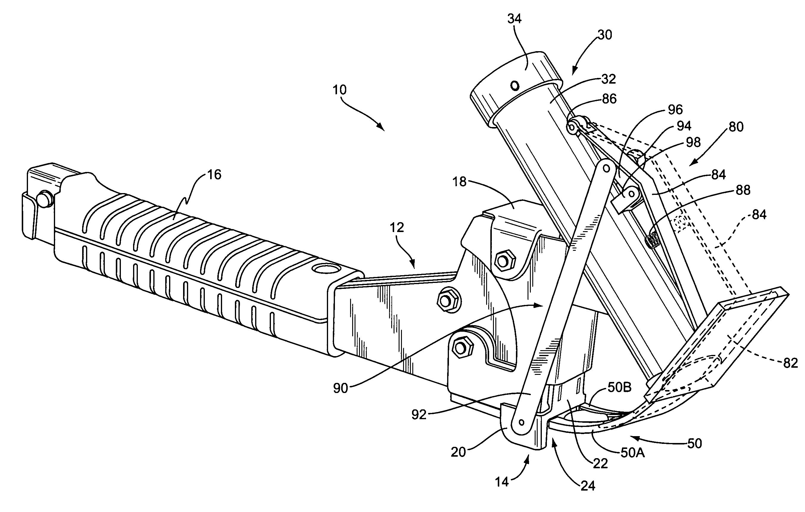
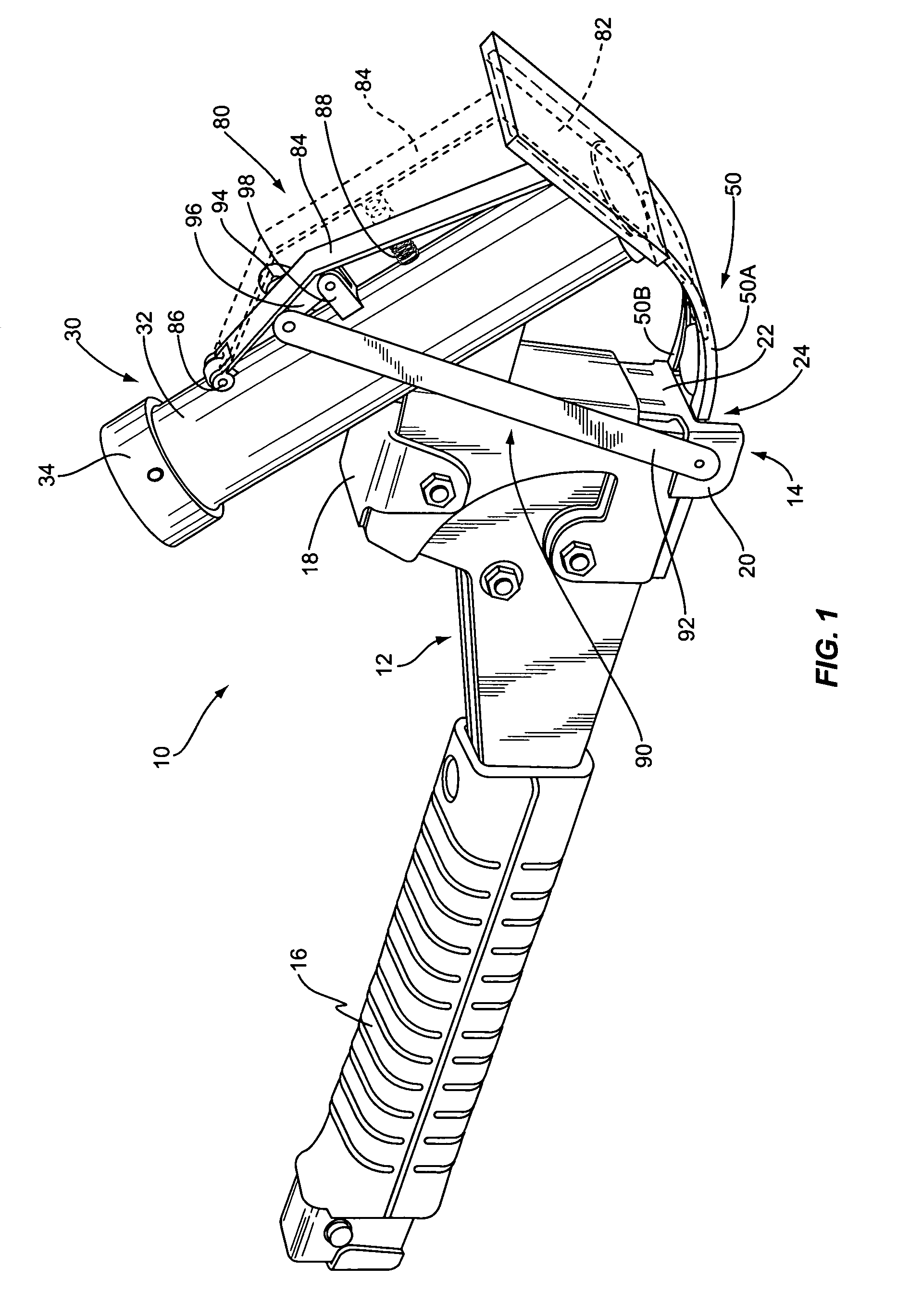
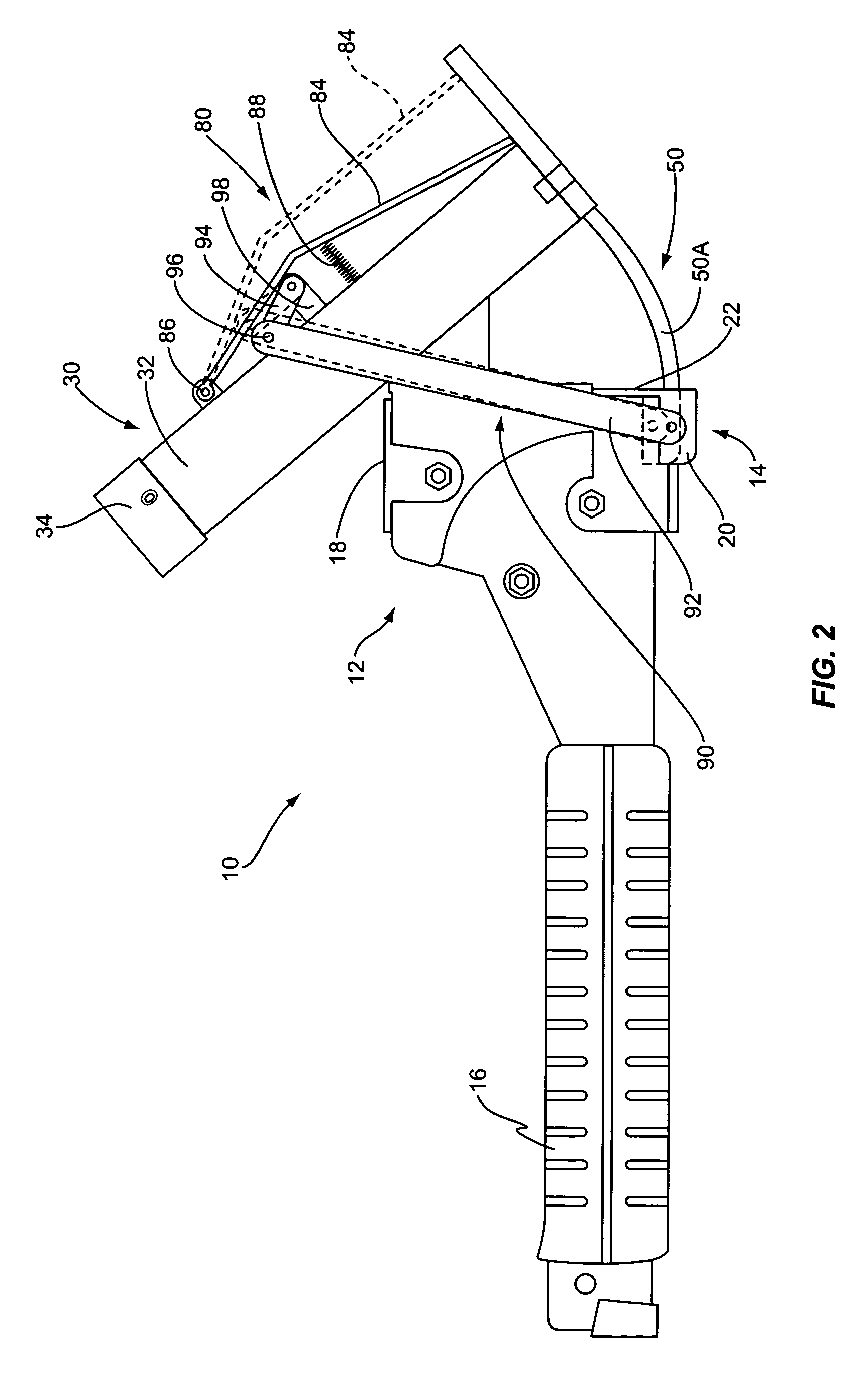
[0014]With further reference to the drawings, the combination staple gun and cap feeding device of the present invention is shown therein and indicated generally by the numeral 10. Basically this device comprises two main assemblies, a staple gun and a cap feeding device indicated generally by the numeral 30. The staple gun portion of the device comprises a manually actuated staple gun that includes two movable portions, a main body indicated generally by the numeral 12 and a movable member indicated generally by the numeral 14. Details of the staple gun itself are not dealt with herein because such is not per se material to the present invention and further, manual staple guns and even automatic or semi-automatic staple guns are well know in the art. For example, note the disclosures found in U.S. Pat. Nos. 6,302,310; 6,543,666; 6,598,776; and 5,328,075. The disclosures of these patents are expressly incorporated herein by reference.

[0015]In any event, reviewing the basic structure...


PUM


Abstract

A combination manual staple gun and a cap feeding device comprises a staple gun having a cap feeding device attached thereto. Interconnected between the staple gun and the cap feeding device is an actuating linkage. The actuating linkage is connected to a movable member of the staple gun and is driven in response to the actuation of the staple gun or in response to the staple gun being pressed against a surface for the purpose of shooting a staple into the surface. More particularly, the cap feeder device includes a container for containing a stack of caps and a cap feeder or feeding mechanism for engaging one cap at a time and directing the cap towards a cap ejection area associated with a staple gun in response to the connecting or actuating linkage being actuated.

Description

FIELD OF THE INVENTION[0001]The present invention relates to staple guns and more particularly to a staple gun having a cap feeding device for automatically feeding one cap at a time to the staple gun such that when the staple gun is actuated or fired a staple is directed through the cap.BACKGROUND OF THE INVENTION[0002]It is known to use nail guns to attach roofing material such as tarpaper to the roof of a structure. It is also known to use small plastic caps to engage and hold tarpaper on the roof. Many such caps include nails prepositioned in the caps. A roofer will typically use a hammer and manually drive the prepositioned nail into the roof, securing the cap over the tarpaper in the process. This is a time consuming, laborious and expensive process. It is not easy for a roofer to stand on an inclined roof, and manually hold a supply of such caps and at the same time secure them into the roof structure.[0003]It is known to provide cap feeding devices for employment with nail g...

Claims


Application Information

Patent Timeline
Patent Type & Authority Patents(United States)
IPC IPC(8): E21B7/00B25C5/11B25C5/16
CPCB25C5/11B25C5/1693
Inventor RIGGS, GREGORY SCOTT
Owner SDGI HLDG
Why Eureka
Try Eureka